
Thin and long part assembling method

An assembly method and technology for long parts, applied in the field of parts positioning, can solve the problems of long cycle, poor rigidity, and difficulty in ensuring assembly accuracy.

Inactive Publication Date: 2015-06-24
SHENYANG AIRCRAFT CORP
View PDF5 Cites 9 Cited by
  • Summary
  • Abstract
  • Description
  • Claims
  • Application Information

AI Technical Summary

Problems solved by technology

[0002] The manufacturing principle of the preliminary work makes the analog quantity transfer manufacturing method. This method is characterized by low assembly efficiency and poor precision, and requires more second-type assembly tools, such as first-level assembly platforms, spirit levels, bent plates, dial indicators, and dial indicators. Blocks, height rulers, square boxes and other tools require operators with high quality who can skillfully use these tools
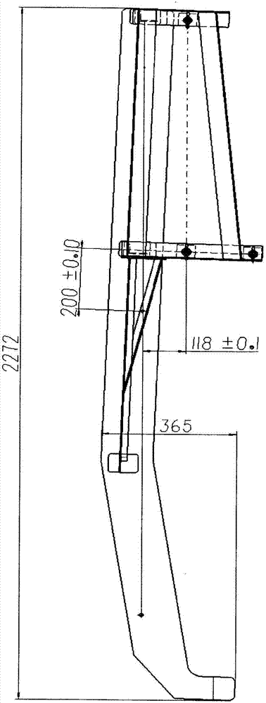
E.g figure 1 and figure 2 The difficulties in the assembly of the calibration fixture are as follows: 1) The part to be positioned is a thin and slender part, which is characterized by relatively good flexibility, but its rigidity is relatively poor, and it is easy to deform, so it needs to be strengthened; 2) According to the traditional It takes a long time to execute the assembly method, and the final assembly accuracy is difficult to guarantee
In the future, due to differences in equipment used by inspectors and assemblers, the tooling may be out of tolerance during inspection, and the assembly accuracy needs to be improved again to eliminate the above reasons

Method used


Image

  • Thin and long part assembling method
  • Thin and long part assembling method
  • Thin and long part assembling method

Examples


Embodiment Construction

[0016] Such as image 3 As shown, an assembly method of thin, thin and long parts includes the following steps:

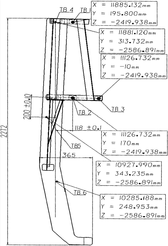
[0017] 1) Use the original 2 holes of the model as the reference hole and add 1 hole as the position measurement hole of the model. The holes of the model and the frame have relative position dimensions of 200±0.1, 118±0.1, 164.95±0.1, and respectively Set to TB4, TB5 and TB6;

[0018] 2) Three holes are drilled by numerical control at three different positions on the frame as the reference holes for establishing the reference coordinate system, and are set as TB1, TB2 and TB3 respectively;

[0019] 3) Set a bushing on the hole of TB1-TB6, and the tool ball of the laser tracker is installed in the bushing, and the ground passing through the bushing is attached to the upper surface of the hole, such as Figure 4 As shown, thus ensuring that the tool ball is installed vertically to the upper surface of the hole;

[0020] 4) In the theoretical state, TB1-TB6 are in...


PUM


Abstract

The invention relates to a thin and long part assembling method. The thin and long part assembling method comprises the following steps of 1 forming position measuring holes TB4, TB5 and TB6 of a sample plate, 2 drilling three holes in a frame and using the three holes as reference holes TB1, TB2 and TB3 for establishing a reference coordinate system, 3 arranging tool balls on the holes TB1, TB2, TB3, TB4, TB5 and TB6, 4 actually measuring values of the tool balls to obtain the positions of the holes TB1, TB2 and TB3, utilizing laser tracker software to perform fitting on theoretical tool ball values and actually-measured values to obtain tool balls TB1, TB2 and TB3 and establishing a three-dimensional coordinate system with the tool balls TB1, TB2 and TB3 as references, 5 reading the actual positions of the measuring holes TB4, TB5 and TB6 through the tool balls and comparing the actual positions with theoretical positions after the coordinate system is established, adjusting the assembling position of the sample plate according to obtained difference values and finally meeting the assembling accuracy requirement. By means of the thin and long part assembling method, assembling accuracy can be improved, an assembling period can be shortened, manpower is decreased, and accordingly company's benefit is improved.

Description

technical field [0001] The invention relates to an assembly method of thin, thin and long parts, which belongs to a part positioning method. Background technique [0002] The manufacturing principle of the preliminary work makes the analog quantity transfer manufacturing method. This method is characterized by low assembly efficiency and poor precision, and requires more second-type assembly tools, such as first-level assembly platforms, spirit levels, bent plates, dial indicators, and dial indicators. Blocks, height rulers, square boxes and other tools require operators with high quality and proficiency in using these tools. E.g figure 1 with figure 2 The difficulties in the assembly of the calibration fixture are as follows: 1) The part to be positioned is a thin and slender part, which is characterized by relatively good flexibility, but its rigidity is relatively poor, and it is easy to deform, so it needs to be strengthened; 2) According to the traditional To implem...

Claims


Application Information

Patent Timeline
IPC IPC(8): G01B11/00B23P19/00
Inventor 李涛
Owner SHENYANG AIRCRAFT CORP
Learn More