
Cooling water circulation system applicable to high-flow test platform

A technology of cooling water system and test bench, which is applied in the direction of measuring device, engine test, machine/structural component test, etc. It can solve the problem that water cannot be replenished in time, and achieve the effect of reducing workload, simplifying the system and reducing damage

Inactive Publication Date: 2015-06-24
BEIHANG UNIV
View PDF7 Cites 5 Cited by
  • Summary
  • Abstract
  • Description
  • Claims
  • Application Information

AI Technical Summary

Problems solved by technology

[0003] The purpose of the present invention is to solve the above problems and propose a cooling water circulation system suitable for large-flow test benches, which eliminates the problem that water cannot be replenished in time during the process of gas pressurization, and simplifies the system equipment

Method used


Image

  • Cooling water circulation system applicable to high-flow test platform

Examples


Embodiment Construction

[0023] The present invention will be further described in detail with reference to the accompanying drawings and embodiments.

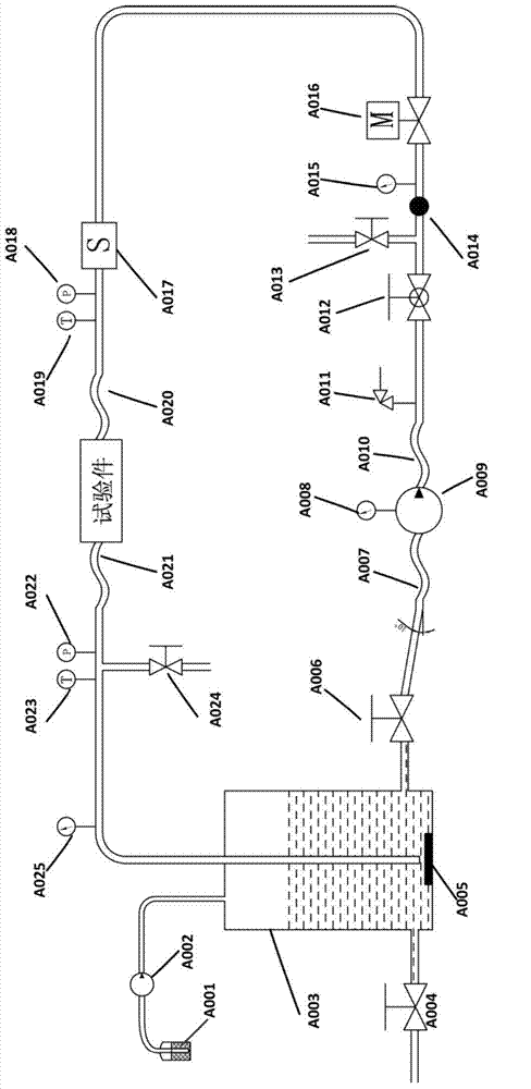
[0024] The present invention is a cooling water system suitable for large flow test benches, such as figure 1 As shown, specifically:

[0025] The barreled distilled water A001 is connected to the small water pump A002, and the water tank A003 is connected with the small water pump A002, the manual stop valve A004, and the manual stop valve A006. The damping block A005 is placed at the bottom of the water tank A003. Block A005 is located directly below the water pipe, and maintains a certain space distance to release the pressure of the distilled water coming out of the return pipe to prevent it from impacting the water tank A003. The water pipe is equipped with a pressure sensor A022, a temperature sensor A023 and a pressure gauge A025 to detect Distilled water state parameters, and also set a three-way connection manual shut-off valve A024, manual ...


PUM


Abstract

The invention discloses a cooling water circulation system applicable to a high-flow test platform. The back of barreled distilled water is connected with a small water pump. The periphery of a water tank is connected with the small water pump, a first manual stop valve and a second manual stop valve. A damping block is placed at the bottom of the water tank. A water pipe in the water tank is connected with a first hose. The damping block is located under the water pipe. A first pressure sensor, a first temperature sensor and a first pressure meter are arranged on the water pipe and used for detecting state parameters of the distilled water. The water pipe is provided with a tee joint connected with a third manual stop valve. The second manual stop valve is connected with a second hose. A water inlet of a high-pressure water pump is connected with the second hose. A water outlet of the high-pressure water pump is connected with a third hose and a second pressure meter. The rear portion of the third hose is provided with a tee joint connected with a safety valve and a flow regulating valve. The flow regulating valve is provided with a tee joint connected with a fourth manual stop valve and a filter. The rear portion of the filter is provided with a tee joint connected with a third pressure meter and a solenoid valve; the rear portion of the solenoid valve is connected with a flowmeter. The outer end of the flowmeter is connected with a fourth hose. A second pressure meter and a second temperature sensor are connected between the flowmeter and the fourth hose. The two ends of a test piece are connected with the fourth hose and the first hose respectively.

Description

technical field [0001] The invention relates to a cooling water system for a test bench of a liquid rocket engine, and is especially suitable for a large-flow reusable engine cooling water supply system. Background technique [0002] As China's aerospace industry moves towards landing on the moon or Mars, the development of high-thrust reusable engines has become an increasingly urgent matter. The main aspect that the reusable engine is different from the previous rocket engine is that each component of the engine has high reliability for the repeated ignition of the engine. In the ground test stage of the engine thrust chamber alone, the high-temperature and high-pressure gas formed by repeated ignition severely scours the inner wall of the combustion chamber. In order to simulate real engine conditions, the thrust chamber needs to be cooled to prevent the high-temperature gas from burning the test piece. Under normal temperature conditions, water is an ideal coolant. It h...

Claims


Application Information

Patent Timeline
Patent Type & Authority Applications(China)
IPC IPC(8): G01M15/02
Inventor 俞南嘉戴健蔡国飙
Owner BEIHANG UNIV
Learn More