A Method for Precisely Locating Defects on Materials in Ultrasonic Testing

An ultrasonic detection and precise positioning technology, which is applied in the analysis of solids using sonic/ultrasonic/infrasonic waves, can solve the problems of difficulty in accurately distinguishing the same defect, unsuitable for batch operation, low efficiency, etc., to reduce positioning errors, avoid mistakes, high efficiency

Active Publication Date: 2017-04-26
AVIC BEIJING INST OF AERONAUTICAL MATERIALS
View PDF8 Cites 0 Cited by
  • Summary
  • Abstract
  • Description
  • Claims
  • Application Information

AI Technical Summary

Problems solved by technology

The above method avoids the defect positioning error caused by manually marking the position of the probe and the deviation of the sound beam from the theoretical position in the contact method detection, and since the time and speed of the sound wave between the defect and the detection surface can generally be accurately measured, it should be possible to obtain High defect positioning accuracy, but this method needs to detect and locate the same defect from three different detection surfaces of the defective sample, which is not suitable for batch operation and low efficiency. When there are multiple dense adjacent defects in the sample at the same time , it will be difficult to accurately distinguish the same defect from different detection surfaces, and it is easy to make mistakes

Method used


Image

  • A Method for Precisely Locating Defects on Materials in Ultrasonic Testing
  • A Method for Precisely Locating Defects on Materials in Ultrasonic Testing
  • A Method for Precisely Locating Defects on Materials in Ultrasonic Testing

Examples


Embodiment 1

[0030] Example 1: Positioning of dense small defects during metallographic dissection of rings

[0031] Combine below Figure 1 ~ Figure 4 , taking the location of a defect in a superalloy ring as an example to illustrate the specific implementation process of the present invention.

[0032] A large number of dense defect signals were found by ultrasonic testing of a high-temperature alloy ring, and it was necessary to determine the nature of the defect through metallographic anatomy. In order to improve the accuracy of defect metallographic sampling, after cutting a section of material containing defects from the ring, the The defect location of segment material is carried out according to the following methods and steps:

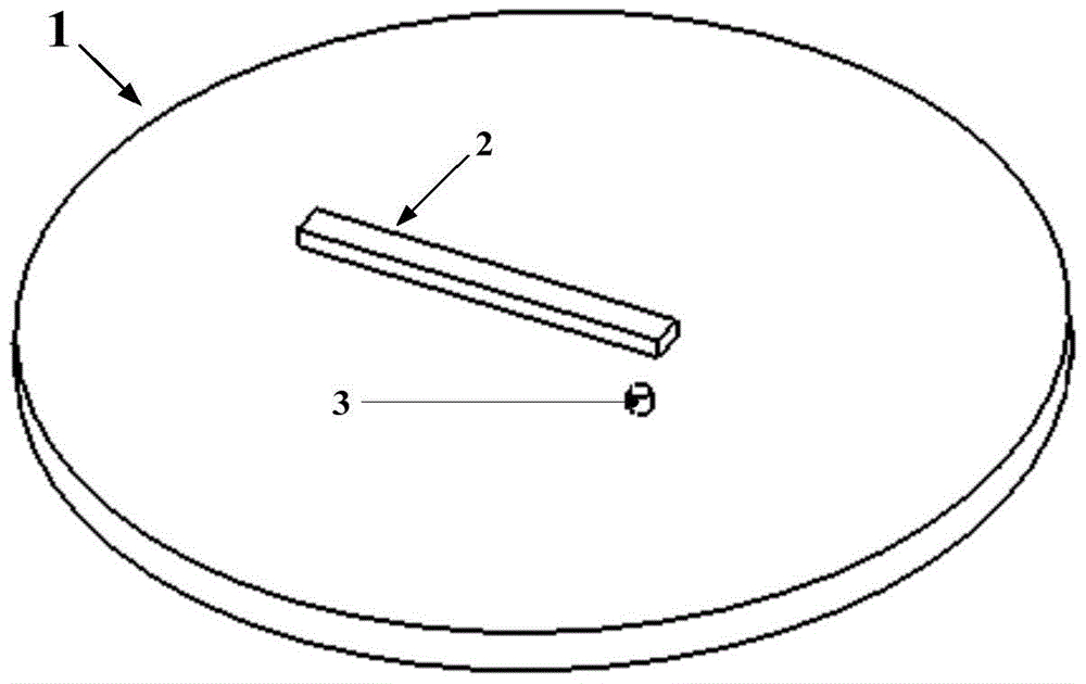
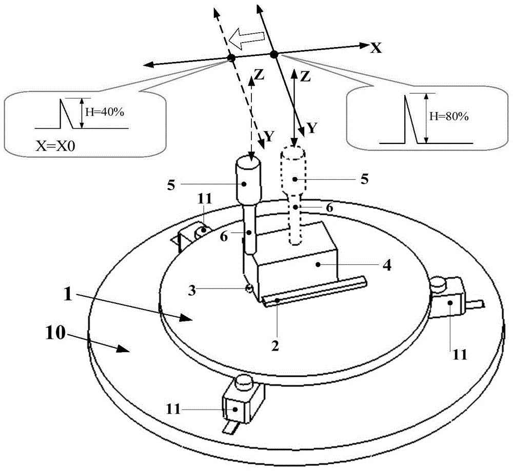
[0033] Step 1. On the horizontal working surface of a circular stainless steel horizontal tray 1 with a diameter of 300mm, a rectangular stainless steel gauge block 2 with a length, width, and height of 100mm, 10mm, and 10mm is fixedly placed, and the lengt...

Embodiment 2

[0042] Example 2: Location of weld defects during mechanical performance testing of welded parts containing defects

[0043] Combine the following Figure 1 ~ Figure 3 , Figure 5 , taking the positioning of defects in a titanium alloy weldment as an example to illustrate the specific implementation process of the present invention.

[0044] In order to establish the acceptance standard for ultrasonic testing of a certain titanium alloy weldment, it is necessary to carry out the mechanical performance test of the defective weld part of the titanium alloy weldment according to the relevant standards. The weld defect of interest is located at the center of the cross-section near half the length of the mechanical performance sample. Since the diameter of the mechanical performance sample at this part is only 5 mm, there is a high requirement for the positioning accuracy of the defect. In view of the above situation, the following defect location methods and steps are adopted:

...


PUM


Abstract

The invention relates to a method for accurately positioning the defects of a material during ultrasonic detection. The method comprises the following steps: firstly, establishing a reference position on a water-immersion based ultrasonic C scanning detection system, and calibrating the coordinate of the reference position in an ultrasonic probe acoustic-beam scanning position coordinate system; then putting the material to be detected in the reference position of the detection system through a positioning reference plane processed on the material to be detected, and carrying out ultrasonic C scanning detection, determining the accurate coordinates of all the defects in the ultrasonic probe acoustic-beam scanning position coordinate system on an ultrasonic C scanned image by using the defect searching function of the water-immersion based ultrasonic C scanning detection system, and deducting the coordinates of the detects on the ultrasonic C scanned image from the coordinate of the reference position on the water-immersion based ultrasonic C scanning detection system to obtain the accurate coordinates of the defects on the positioning reference plane processed on the material to be detected; and finally combining the coordinates of the defects on the positioning reference plane processed on the material to be detected with the depths of the defects read by an ultrasonic defect detection unit on the ultrasonic detection surface of the material to be detected to form the three-dimensional spacial position coordinates of the defects in the material to be detected.

Description

technical field [0001] The invention relates to a method for accurately locating defects on materials in ultrasonic testing, belonging to the technical field of non-destructive testing. Background technique [0002] Nondestructive testing has been widely used in defect detection and quality evaluation of metal products. It is very important to obtain the precise position information of small defects in the material in the non-destructive testing of metal products. It is an important basis for guiding the metallographic anatomy of materials and verifying the effectiveness of the testing process. It is an important basis for the material manufacturing department to analyze the nature of defects and guide the improvement of product manufacturing processes. For reference, it is also in hot research fields such as structural life prediction and material non-destructive evaluation. Effectively carry out sampling and mechanical performance testing of material defects important pre...

Claims


Application Information

Patent Timeline
Patent Type & Authority Patents(China)
IPC IPC(8): G01N29/06
Inventor 王东升唐佳徐娜史亦韦王铮何方成
Owner AVIC BEIJING INST OF AERONAUTICAL MATERIALS
Why Eureka
Try Eureka