Chip electronic component and manufacturing method thereof

A technology of electronic components and manufacturing methods, applied in the direction of inductance/transformer/magnet manufacturing, coil manufacturing, electrical components, etc., which can solve the problems of high aspect ratio of short circuit height of coils, increase of spacing between coils, etc.

Active Publication Date: 2015-06-24
SAMSUNG ELECTRO MECHANICS CO LTD
View PDF6 Cites 12 Cited by
  • Summary
  • Abstract
  • Description
  • Claims
  • Application Information

AI Technical Summary

Problems solved by technology

However, in this case, since the plating resist needs to have a predetermined width or more in order to maintain the shape of the plating resist, the spacing between the coil parts increases.
[0011] In addition, when the electroplating method is performed

Method used


Image

  • Chip electronic component and manufacturing method thereof
  • Chip electronic component and manufacturing method thereof
  • Chip electronic component and manufacturing method thereof

Examples


Embodiment Construction

[0038] Exemplary embodiments of the present disclosure will now be described in detail with reference to the accompanying drawings.

[0039] This disclosure, however, may be embodied in many different forms and should not be construed as limited to the specific embodiments set forth herein. Rather, these embodiments are provided so that this disclosure will be thorough and complete, and will fully convey the scope of the disclosure to those skilled in the art.

[0040] In the drawings, the shapes and dimensions of elements may be exaggerated for clarity, and the same reference numerals will be used throughout to designate the same or like elements.

[0041] chip electronic components

[0042] Hereinafter, a chip type electronic component according to an exemplary embodiment of the present disclosure will be described. Specifically, a thin inductor will be described, but the present disclosure is not limited thereto.

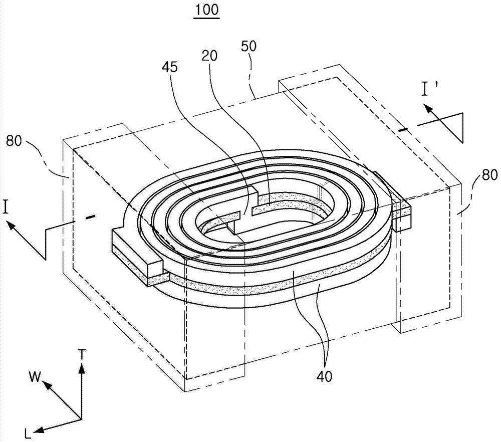
[0043] figure 1 is a schematic perspective view showi...


PUM

PropertyMeasurementUnit
Widthaaaaaaaaaa
Widthaaaaaaaaaa

Abstract

The present invention provides a chip electronic component and a manufacturing method thereof, more specifically a chip electronic component having an inner coil structure capable of preventing short circuit between the coil portions by increasing the thickness of the coil relative to the width of the coil and implementing a high aspect ratio (AR), and a manufacturing method thereof.

Description

[0001] This application claims the benefit of Korean Patent Application No. 10-2013-0158080 filed in the Korean Intellectual Property Office on December 18, 2013, the disclosure of which is hereby incorporated by reference. technical field [0002] The present disclosure relates to a chip electronic component and a manufacturing method thereof. Background technique [0003] Inductors, one of chip electronic components, are representative passive components that form electronic circuits together with resistors and capacitors to remove noise. Such an inductor is combined with a capacitor using electromagnetic properties to constitute a resonance circuit, a filter circuit, etc. that amplify a signal of a specific frequency band. [0004] Recently, since miniaturization and slimming of information technology (IT) devices such as various communication devices, display devices, etc. have been accelerated, miniaturization of various elements such as inductors, capacitors, transisto...

Claims


Application Information

Patent Timeline
IPC IPC(8): H01F17/04H01F27/28H01F41/00H01F41/04
CPCH01F27/006H01F27/2804H01F27/292H01F27/33H01F41/06
Inventor 郑东晋
Owner SAMSUNG ELECTRO MECHANICS CO LTD
Why Eureka
Try Eureka