

Sending and receiving method, base station and terminal for synchronous wave beam forming signals
A beamforming and transmission method technology, applied in the field of high-frequency communication, can solve the problems of selection and normal communication, the inability of the base station and the terminal to perform beamforming weights, and the inability of the base station and the terminal to reach.
- Summary
- Abstract
- Description
- Claims
- Application Information
AI Technical Summary
Problems solved by technology
Method used
Image

Examples
Embodiment 1
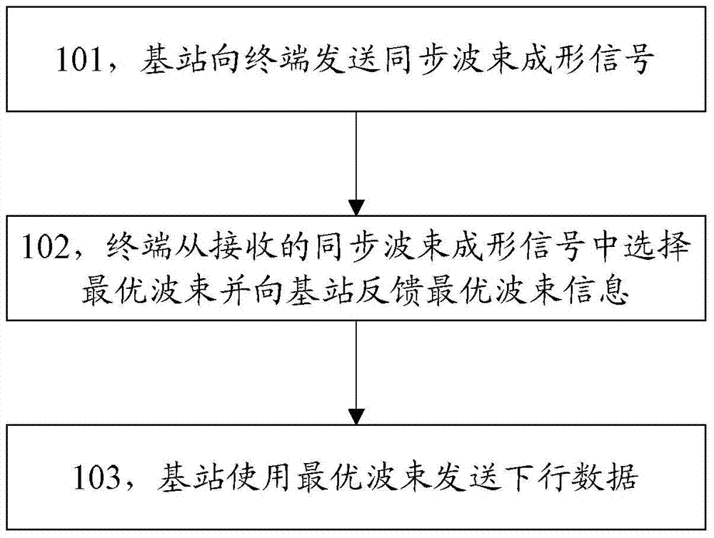
[0071] The base station periodically sends synchronous beamforming signals on predefined time-frequency resources, and divides the sequence of the synchronous beamforming signals into M beam groups, each of which includes N m (The value of m is 1~M) sequences. The beam group index (inter-group index) is used to indicate the cell identity, and the sequence index (intra-group index) in the beam group is used to indicate the beam index in the cell, then M beam groups and each group N m The sequence constitutes a total of sequences (M is a positive integer). According to the number M of beam groups, the inter-group index can be set to 1, 2...M, or 0, 1...M-1; according to the number N of sequences in each beam group m , you can set the index within the group to 1, 2...N m , can also be set to 0, 1...N m -1, such as the structures shown in Table 1-1 and Table 1-2.
[0072]
[0073] Table 1-1
[0074]
[0075] Table 1-2
[0076] The above two setting modes of the inter...
Embodiment 1-1
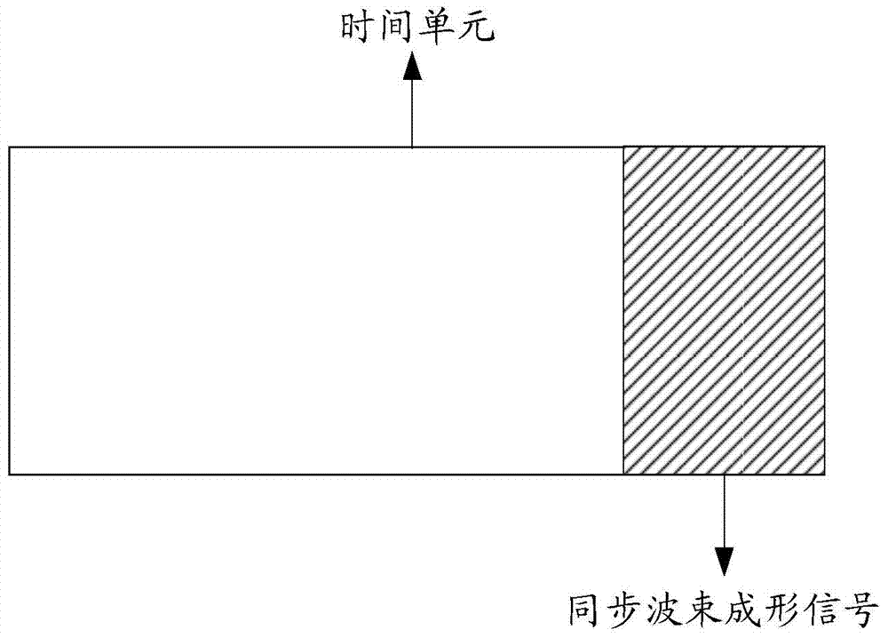
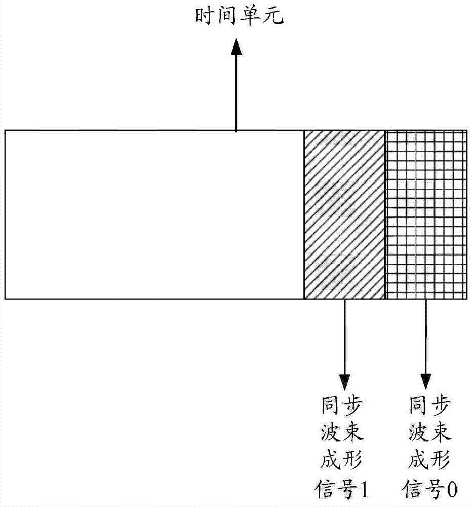
[0080] Such as figure 1 As shown in , it is assumed that the base station periodically transmits a synchronous beamforming signal within a predefined time unit. The sequence of the synchronous beamforming signal is divided into 63 beam groups, and each beam group includes 8 sequences, the inter-group sequence index is used to indicate the cell identity, and the intra-group sequence index is used to indicate the beam index in the cell. Groups and 8 sequences per group constitute a total of 504 sequences.
[0081] The terminal detects the sequence of the synchronous beamforming signal sent by the base station. When the terminal detects the optimal sequence, the terminal detects the corresponding inter-group index and intra-group index, thereby identifying the corresponding cell ID and beam index. After obtaining the beam index, the terminal directly or indirectly feeds back the beam index through the uplink. After obtaining the beam index fed back by the terminal, the base sta...
Embodiment 1-2
[0084] Such as figure 1 As shown in , it is assumed that the base station periodically transmits a synchronous beamforming signal within a predefined time unit. The sequence of the synchronous beamforming signal is divided into 14 beam groups, and each beam group includes 36 sequences. The inter-group sequence index is used to indicate the cell identity, and the intra-group sequence index is used to indicate the beam index in the cell. Groups and 36 sequences per group constitute a total of 504 sequences.
[0085] The terminal detects the sequence of the synchronous beamforming signal sent by the base station. When the terminal detects the optimal sequence, the terminal detects the corresponding inter-group index and intra-group index, thereby identifying the corresponding cell ID and beam index. After obtaining the beam index, the terminal directly or indirectly feeds back the beam index through the uplink. After obtaining the beam index fed back by the terminal, the base s...
PUM
 Abstract
Description
Claims
Application Information