Wearable bio-electricity signal collection device
A bioelectric signal and acquisition device technology, applied in medical science, sensors, diagnostic recording/measurement, etc., can solve the problems of medical treatment, psychological cognition, poor fit of rigid support structure, poor contact between electrodes and skin, etc. problem, to achieve the effects of small impedance change over time, low noise, and stable skin interface
- Summary
- Abstract
- Description
- Claims
- Application Information
AI Technical Summary
Problems solved by technology
Method used
Image
Examples
Embodiment 1
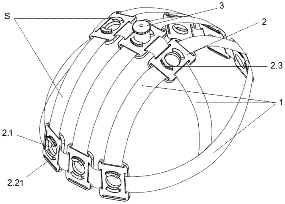
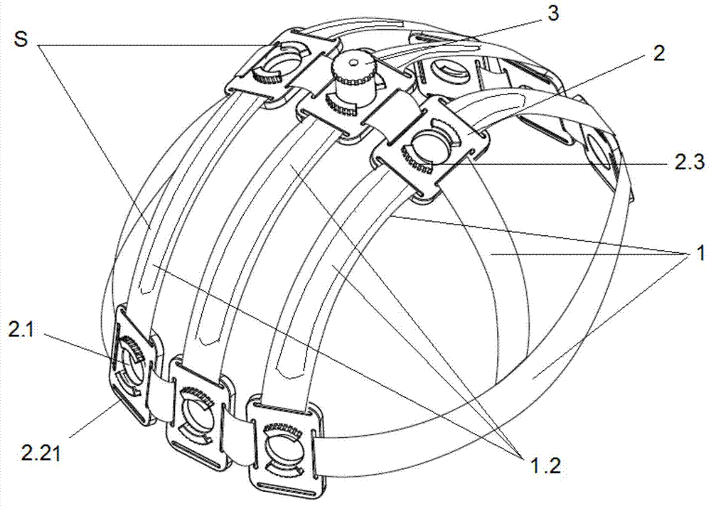
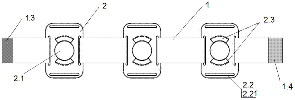
[0045] Example 1: is a basic embodiment of the present invention. As shown in the figure, a wearable bioelectrical signal acquisition device is composed of an electrode support assembly S connected to an electrode 3; the electrode support assembly S includes a connecting belt 1 and a fixing piece 2; the middle part of the fixing piece 2 There are electrode installation holes 2.1, and there are card slots 2.2 for fixing the connection belt 1 at the side; there are at least one pair of two card slots 2.2, which are symmetrically distributed on both sides of the electrode installation holes 2.1; the fixing member 2 passes through the The slot 2.2 is fixed at one end or both ends or in the middle of the connecting belt 1; the connecting belt 1 is an elastic flat belt, and the fixing part 2 is a rigid flat block.
Embodiment 2
[0046] Example 2: is a further example. On the basis of Embodiment 1, the connecting belt 1 is an elastic flat belt that can pass through the slot 2.2 at one or both ends, or the entire connecting belt can pass through the slot 2.2, and there is a hole in the middle that can enter the electrode 3. Elastic flat strip for holes 1.1 or through slots 1.2. Such as Figure 1.1 - As shown in -5, the described card slot 2.2 is a flat single-port card slot 2.21; or as Image 6 The shown card slot 2.2 is a dual-port card slot 2.22; the dual-port card slot 2.22 is composed of two adjacent single-port card slots 2.21 juxtaposed. Such as Figure 8 , 9 , 10, the connection between the electrode 3 and the electrode installation hole 2.1 is clamping, and can also be a threaded connection; the clamping is the fixed boss 2.3 on the inner hole side wall of the electrode mounting hole 2.1 end face The bayonet slot 2.31 is meshed with the bayonet 3.1 on the outer circumference of the electro...
Embodiment 3
[0047] Example 3: is a further example. The difference with embodiment 2 is: as Figure 1.1 As shown in -6, the fixing member 2 is a square rigid flat block, each side has a slot 2.2, a total of 2 pairs of 4 symmetrically distributed on both sides of the electrode installation hole 2.1.
PUM
 Abstract
Description
Claims
Application Information
 - R&D
- Intellectual Property
- Life Sciences
- Materials
- Tech Scout
- Unparalleled Data Quality
- Higher Quality Content
- 60% Fewer Hallucinations
Browse by: Latest US Patents, China's latest patents, Technical Efficacy Thesaurus, Application Domain, Technology Topic, Popular Technical Reports.
© 2025 PatSnap. All rights reserved.Legal|Privacy policy|Modern Slavery Act Transparency Statement|Sitemap|About US| Contact US: help@patsnap.com


