A wiring method of a printed circuit board

A printed circuit board and wiring technology, applied in the direction of printed circuits, printed circuits, printed circuit components, etc., can solve the problems of inability to meet the requirements of high-frequency bus signal transmission and signal integrity, inconsistent dielectric constant of transmission lines, and signal delay Inconsistency and other problems, to achieve the effect of improving time delay inconsistency, improving impedance consistency, and reducing impedance fluctuations

Active Publication Date: 2019-07-12
GUANGZHOU FASTPRINT CIRCUIT TECH +2
View PDF4 Cites 0 Cited by
  • Summary
  • Abstract
  • Description
  • Claims
  • Application Information

AI Technical Summary

Problems solved by technology

[0008] At present, most wiring strategies are to route the transmission line in the system bus at an angle of 0° or 90° to the edge of the substrate, which will cause the direction of the transmission line to be parallel to the warp and weft of the glass fiber, so that it may appear that the transmission line is directly above the warp and weft or the transmission line In extreme cases between two warp and weft yarns, such as figure 1 As shown, the transmission line 103 is located between two warp glass fiber bundles 101, the transmission line 104 is located directly above a warp glass fiber bundle 101, the transmission line 105 is located directly above a weft glass fiber bundle 102, and the transmission line 106 is located between two Between the glass fiber bundles 101 in the weft direction, in this way, the actual dielectric constants of different transmission lines are inconsistent, resulting in differences in impedance at different positions on the board surface. When a pair of differential transmission lines is distributed directly above the glass fiber bundles, and When between glass fiber bundles, due to the difference in dielectric constant between the two, the signal delay will be inconsistent, causing the signal to be skewed and distorted (Skew)
As the frequency of signal transmission is getting higher and higher, the requirements for PCB impedance control accuracy are getting higher and higher. This wiring method cannot meet the signal transmission and signal integrity requirements of high-frequency buses.

Method used


Image

  • A wiring method of a printed circuit board
  • A wiring method of a printed circuit board
  • A wiring method of a printed circuit board

Examples


no. 2 example

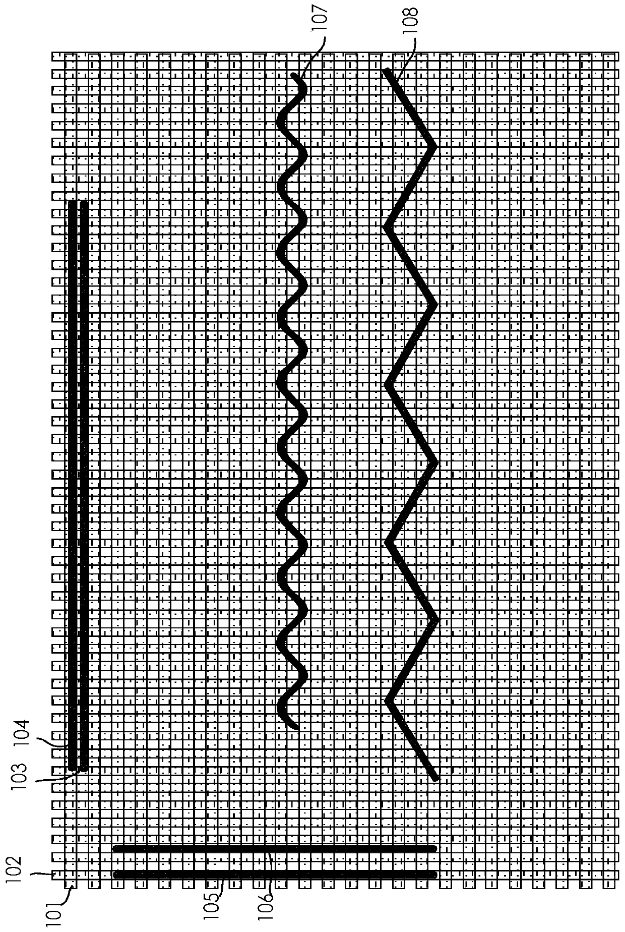
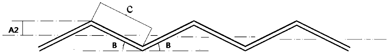
[0033] Such as figure 1 with image 3 As shown, the wiring method of the printed circuit board includes:

[0034] A transmission line 108 is arranged on the substrate. When the length of the transmission line 108 is greater than 1 inch, the transmission line 108 is in the shape of a symmetrical triangular wave curve. is B, where 0°

[0035] When wiring in the present invention, when the length of the transmission line 108 is greater than 1 inch, the transmission line 108 is arranged in a symmetrical triangular wave curve, so that the influence of the inhomogeneity of the PCB substrate medium on the transmission line 108 can be weakened, especially for high-speed PCBs. This wiring method can reduce the influence of the dielectric constant fluctuation of the dielectric layer on the impedance and signal transmission delay, reduce the impedance fluctuation of the same transmission line, improve the impedance consistency between different transmission lines, and significan...


PUM


Abstract

The invention discloses a wiring mode for a printed circuit board. The wiring mode comprises the steps that a transmission line is arranged on a substrate; when the length of the transmission line is greater than 1 inch, the transmission line adopts a sine wave curve shape; the wave crest of the sine wave curve is greater than the maximum glass fiber beam spacing; the wavelength of the sine wave curve is greater than 3H, wherein H refers to the distance from the transmission line to a reference plane. The invention also discloses a wiring mode for the printed circuit board. The wiring mode comprises the steps a the transmission line is arranged on a substrate; when the length of the transmission line is greater than 1 inch, the transmission line adopts a symmetrical triangular wave curve shape; the wave crest A2 of the symmetrical triangular wave curve is greater than the maximum glass fiber beam spacing; and the break angle of the sine wave curve is B, wherein B is greater than 0 degree and less than 45 degrees. According to the wiring modes for the printed circuit board, the impedance fluctuations of the same transmission line can be reduced, and the impedance consistency of different transmission lines can be improved.

Description

technical field [0001] The invention relates to the field of printed circuit board design, in particular to a wiring method of a printed circuit board. Background technique [0002] The main materials used in printed circuit boards include substrate materials (copper clad laminates) and prepregs. Among them, the substrate materials (copper clad laminates) are composed of resin, glass fiber cloth, and copper foil, and the prepregs are composed of resin and glass fiber cloth. Glass fiber cloth is the skeleton of copper clad laminate and prepreg, which can improve the strength of the substrate material while maintaining its structural stability. At present, the most commonly used electronic glass fiber cloth in copper clad laminates and prepregs is made of interwoven warp and weft yarns. This glass fiber cloth has a grid structure, and the glass fiber content is high at the interlaced points of warp and weft yarns. The content is low, while the gaps between the warp and weft y...

Claims


Application Information

Patent Timeline
Patent Type & Authority Patents(China)
IPC IPC(8): H05K1/02
CPCH05K1/0296H05K2201/09263
Inventor 程柳军王红飞陈蓓
Owner GUANGZHOU FASTPRINT CIRCUIT TECH
Why Eureka
Try Eureka