Direct-pushing-type numerically-controlled-lathe feeding-discharging assisting system

A CNC lathe, direct push technology, applied in the direction of metal processing mechanical parts, metal processing, automatic in/out of workpieces, etc., can solve the problems that the jaw action depends on electrical control, technology is prohibitive, and the action is complicated, etc., to achieve material loading and The blanking process is simple, the way of loading and unloading is simplified, and the failure rate is low.

Active Publication Date: 2015-07-01
湖北信友汽车零部件有限公司
View PDF8 Cites 9 Cited by
  • Summary
  • Abstract
  • Description
  • Claims
  • Application Information

AI Technical Summary

Problems solved by technology

First, in order to realize loading, the jaws must be moved back and forth, left and right, and up and down to align the workpiece with the chuck of the lathe, and the action is complicated; second, the clamping of the feeding system must rely on the jaws (pneumatic fingers) to achieve ; Third, the current standard 90-degree transposition wrist plus two two-finger grippers has a complex structure and a large volume, which is prone to interference; fourth, the blanking of the workpiece also depends on the grippers, and the speed is slow; fifth , the gripper (pneumatic finger) is a precision component, which is easily damaged by wear and tear, and the action of the gripper depends on electrical control
The above five shortcomings have restricted the development of manipulators in the field of automatic loading and unloading of CNC lathes. Due to the high initial investment cost and the high cost of replacing grippers, many companies are discouraged from this technology.

Method used


Image

  • Direct-pushing-type numerically-controlled-lathe feeding-discharging assisting system
  • Direct-pushing-type numerically-controlled-lathe feeding-discharging assisting system
  • Direct-pushing-type numerically-controlled-lathe feeding-discharging assisting system

Examples


Embodiment Construction

[0025] The present invention will be further described in detail below in conjunction with the accompanying drawings, but does not constitute any limitation to the present invention. Similar component numbers in the accompanying drawings represent similar components. As mentioned above, the present invention provides a direct push CNC lathe auxiliary loading and unloading system, which has a simple structure and is easier to operate and use.

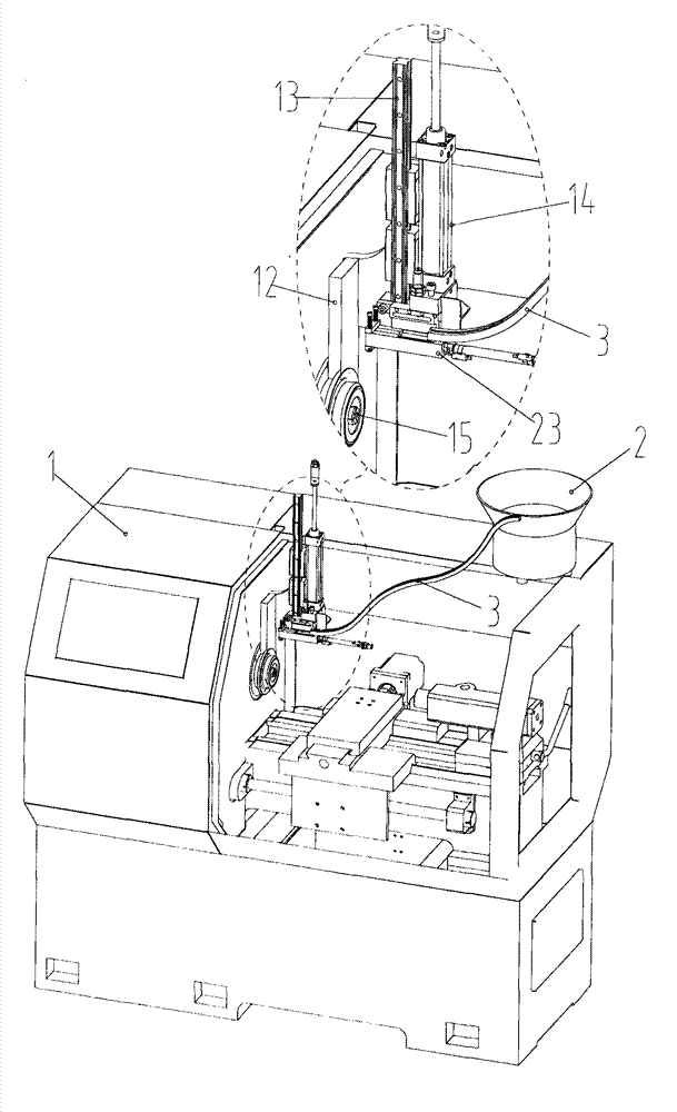
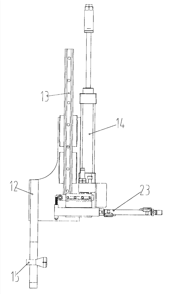
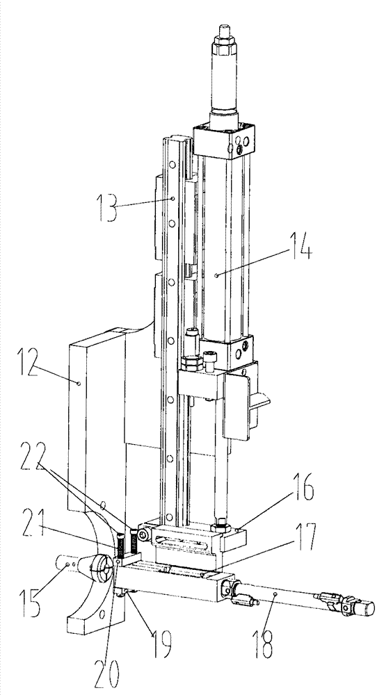
[0026] figure 1 It is a schematic diagram of the structure of the direct-push CNC lathe auxiliary loading and unloading system installed on the CNC lathe of the present invention, figure 2 , 3 It is a structural schematic diagram of the auxiliary loading and unloading system of the direct-push CNC lathe of the present invention, Figure 4 It is a structural schematic diagram of the feeding mechanism of the direct push CNC lathe auxiliary loading and unloading system of the present invention, Figure 5 It is a structural schematic dia...


PUM


Abstract

The invention relates to a machining device, in particular to an automatic feeding-discharging system of a numerically-controlled lathe. The direct-pushing-type numerically-controlled-lathe feeding-discharging assisting system comprises a vibrating disc, a feeding mechanism, a discharging mechanism, a linear guide rail, a lifting air cylinder and a support. The support is fixedly connected to the numerically-controlled lathe. The linear guide rail is movably connected to the support, a lifting plate is fixedly connected with the tail end of the linear guide rail, the lifting air cylinder is fixedly connected to the support, and a piston rod of the lifting air cylinder is fixedly connected with the lifting plate. The feeding mechanism is fixedly connected to the lifting plate. A technology for achieving automatic feeding and automatic discharging of the numerically-controlled lathe is disclosed. By means of the direct-pushing-type numerically-controlled-lathe feeding-discharging assisting system, clamping jaws widely used in the industry are omitted, a simpler and more durable direct-pushing type mechanism is developed, and the feeding process and the discharging process of workpieces on a chuck of the numerically-controlled lathe are achieved. Motions are accurate in the feeding process, and the speed is high in the discharging process.

Description

technical field [0001] The invention relates to a mechanical manufacturing equipment, in particular to an automatic loading and unloading system of a numerically controlled lathe. Background technique [0002] The advent of the 21st century has driven the rapid development of science and technology, and at the same time made human manufacturing to a higher level. The application of manipulators and industrial robots has made the manufacturing industry more automated. The development and application of various manipulators have made us The country's manufacturing industry has moved to the forefront of the world. [0003] In the existing mechanical production, the manipulator is used to replace the manual operation, realize the mechanization and automation of production, and ensure the personal safety of the operator, so it is widely used. At present, the manipulators used on CNC lathes generally have the function of moving the jaws back and forth, left and right, and up and ...

Claims


Application Information

Patent Timeline
Patent Type & Authority Applications(China)
IPC IPC(8): B23B15/00
CPCB23Q7/00B23Q7/06B23Q2707/003
Inventor 余胜东
Owner 湖北信友汽车零部件有限公司
Why Eureka
Try Eureka