
Method for manufacturing holes in different-material laminated structures through automatic drilling and riveting system

A technology of automatic drilling and riveting, laminated structure, applied in aircraft parts, transportation and packaging, etc., can solve the problems of drilling quality degradation, vibration phenomenon, inferiority, etc., achieve high-precision processing, improve drilling quality, and improve processing efficiency Effect

Inactive Publication Date: 2015-07-01
CHENGDU AIRCRAFT INDUSTRY GROUP
View PDF3 Cites 5 Cited by
  • Summary
  • Abstract
  • Description
  • Claims
  • Application Information

AI Technical Summary

Problems solved by technology

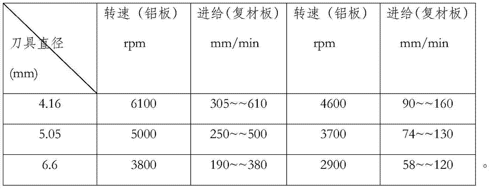
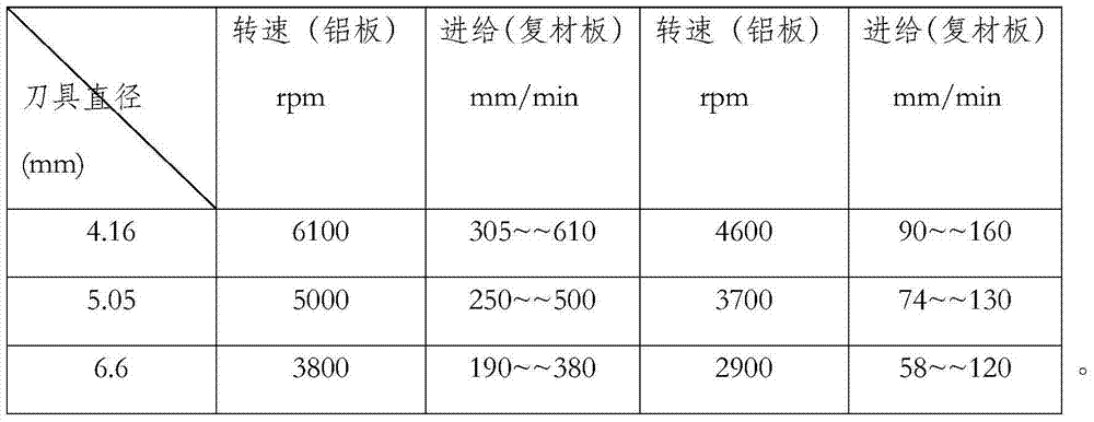
[0005] Because the automatic drilling and riveting system adopts a mechanical arm structure, its structural rigidity is much worse than that of the CNC machine tool system. As a result, if it is subjected to excessive cutting force during processing, it may vibrate, resulting in Drilling quality declines; at the same time, the torque and power of the drilling spindle of the automatic drilling and riveting system are not as good as those of the machining spindle used by the CNC machine tool, making it impossible to operate at a higher speed and feed. To ensure the machining accuracy; these deficiencies brought about by the machining system itself make it necessary to consider the machining parameters and the machining process, choose the machining parameters and targeted machining process different from the conventional CNC machine tools, so as to achieve the The process plan that finally meets the processing requirements

Method used


Image

  • Method for manufacturing holes in different-material laminated structures through automatic drilling and riveting system
  • Method for manufacturing holes in different-material laminated structures through automatic drilling and riveting system
  • Method for manufacturing holes in different-material laminated structures through automatic drilling and riveting system

Examples


Embodiment Construction

[0022] The present invention will be further described in detail below in conjunction with examples, but the embodiments of the present invention are not limited thereto.

[0023] A method for making holes in laminated structures of different materials by using an automatic drilling and riveting system, comprising:

[0024] Before using the automatic drilling and riveting system for test processing, first use the existing CNC processing equipment to conduct experiments, and obtain the corresponding experimental processing parameters;

[0025] Referring to the experimental processing parameters, it is applied to the automatic drilling and riveting system for hole-making tests, so as to obtain the best hole-making processing parameters of the automatic drilling and riveting system.

[0026] In this example, the research on the selection of automatic hole-making processing parameters for different material laminated structures is to obtain a reasonable parameter, which is applied...


PUM


Abstract

The invention discloses a method for manufacturing holes in different-material laminated structures through an automatic drilling and riveting system. The method includes the steps that before the automatic drilling and riveting system is used for testing and machining, existing numerical control machining equipment is firstly used for testing, and corresponding testing and machining parameters are obtained; the testing and machining parameters are referred and are applied to the automatic drilling and riveting system for hole manufacturing tests, and therefore the best hole manufacturing machining parameters of the automatic drilling and riveting system are obtained. By means of the method for manufacturing the holes in the different-material laminated structures through the automatic drilling and riveting system, vertical tail testing pieces and vertical tail products are tested and machined, the machining results meet the examination requirement, and the hole drilling quality is greatly improved compared with the hole drilling quality of manual machining; meanwhile, the machining efficiency is obviously improved, and continuous, efficient and high-accuracy machining of the vertical tail components is achieved.

Description

technical field [0001] The invention relates to the technical field of aircraft manufacturing, in particular to a method for making holes in laminated structures of different materials by using an automatic drilling and riveting system. Background technique [0002] In aircraft manufacturing, the quality of the assembly connection directly affects the fatigue resistance and reliability of the aircraft structure, and the load carried by the aircraft structure is transmitted through the connection, resulting in stress concentration at the connection. According to statistics, 80% of the fatigue cracks are generated in the connection holes, so the connection quality greatly affects the life of the aircraft, and manual drilling and riveting is difficult to guarantee the life requirements. Automatic drilling and riveting can well overcome the problems of low production efficiency of traditional manual drilling and riveting and difficulty in guaranteeing the quality of holes. [0...

Claims


Application Information

Patent Timeline
Patent Type & Authority Applications(China)
IPC IPC(8): B23B35/00
CPCB23B35/00B23B2215/04
Inventor 李建川李辉侯捷
Owner CHENGDU AIRCRAFT INDUSTRY GROUP
Learn More