
Pressure foot system for multifunctional automatic drilling and riveting end effector and working method

An end effector, automatic drilling and riveting technology, applied in the direction of manufacturing tools, metal processing equipment, drilling/drilling equipment, etc., to achieve the effect of optimizing the working environment, improving the efficiency of fine chips, and improving the efficiency of chip suction

Active Publication Date: 2015-07-01
NANJING UNIV OF AERONAUTICS & ASTRONAUTICS
View PDF8 Cites 1 Cited by
  • Summary
  • Abstract
  • Description
  • Claims
  • Application Information

AI Technical Summary

Problems solved by technology

[0002] The development of automated assembly technology in the aviation manufacturing industry has very important economic value and strategic significance. The robot automatic hole-making technology of foreign aircraft manufacturers has matured and been widely put into production. Among them, the automatic hole-making end effector is used for aircraft automatic assembly processing. Although the technological hotspots and cutting-edge fields in the field of manufacturing automation have been widely used in developed countries of aviation manufacturing, due to various reasons, these companies have to keep strict technical confidentiality, and their related core technologies are still in a state of technical blockade, so Research in this field is still in its infancy in my country

Method used


Image

  • Pressure foot system for multifunctional automatic drilling and riveting end effector and working method
  • Pressure foot system for multifunctional automatic drilling and riveting end effector and working method
  • Pressure foot system for multifunctional automatic drilling and riveting end effector and working method

Examples


Embodiment Construction

[0016] The present invention will be described in further detail below in conjunction with the accompanying drawings.

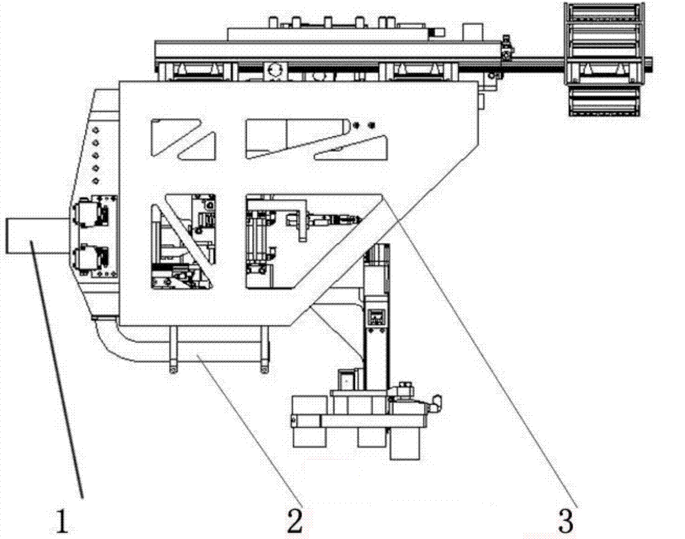
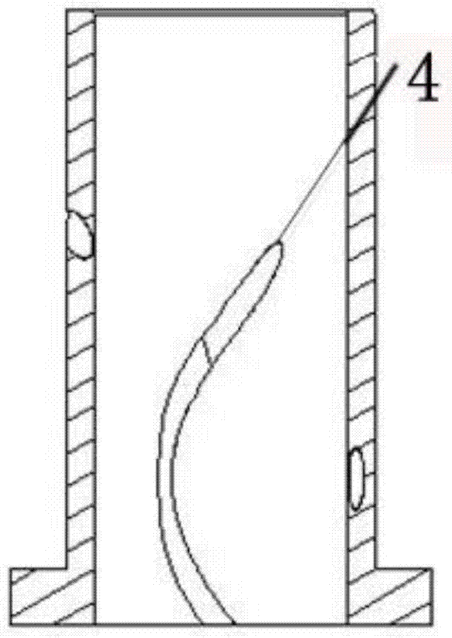
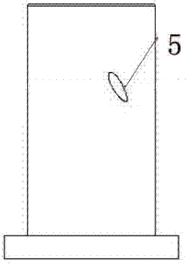
[0017] A pressure foot system for a multifunctional automatic drilling and riveting end effector. The pressure foot system is connected with the outer frame 3 of the end effector by bolts, including a base body, pressure foot 1, and a drive module. The pressure foot 1 is installed on the base body, and the drive module drives The pressure foot 1 works, and the pressure foot system is connected to the vacuum chip suction device through the pipeline 2. There are several air blowing channels 4 inside the base pipe, which cooperate with the vacuum chip suction device to form a chip removal flow field.

[0018] Among them, the structure improvement design in the matrix is ​​used to realize the channel of the internal flow field of the pressure foot; the vacuum chip suction device is connected to suck the chips; the driving module includes a double compression cylin...


PUM


Abstract

The invention relates to a pressure foot system for a multifunctional automatic drilling and riveting end effector. The pressure foot system is connected with the end effector and comprises a base body, a pressure foot and a driving module, wherein the pressure foot is installed on the base body, and the driving module drives the pressure foot to work. The pressure foot system is characterized in that the pressure foot system is connected with a vacuum chipping sucking device through a pipeline, and a plurality of air blowing channels are formed in a base body pipeline and matched with the vacuum chipping sucking device to form a chipping removal flow field. After an upper computer of the end effector gives a machining object attribute, an electromagnetic proportional valve provides pressing force numerical values for a pressing air cylinder, after the pressing air cylinder drives the pressure foot to press a workpiece, the vacuum chipping sucking device is started, a high-pressure environment is formed on an air blowing opening, a low-pressure environment is formed on an air outlet, a cyclone is formed in the three air blowing channels in a spiral state to form the chipping removal flow field, while starting the drilling work, the end effector does the chipping sucking task, and chippings on a machining site are discharged.

Description

technical field [0001] The invention is applied to the field of automatic assembly and hole making of aircraft components, and in particular relates to the design of pressure feet in a robot automatic drilling and riveting system. Background technique [0002] The development of automated assembly technology in the aviation manufacturing industry has very important economic value and strategic significance. The robot automatic hole-making technology of foreign aircraft manufacturers has matured and been widely put into production. Among them, the automatic hole-making end effector is used for aircraft automatic assembly processing. Although the technological hotspots and cutting-edge fields in the field of manufacturing automation have been widely used in developed countries of aviation manufacturing, due to various reasons, these companies have to keep strict technical confidentiality, and their related core technologies are still in a state of technical blockade, so Resear...

Claims


Application Information

Patent Timeline
IPC IPC(8): B23Q3/00B23B47/32
CPCB23B47/34B23Q3/00
Inventor 田威廖文和李震宇陈亚丽张霖
Owner NANJING UNIV OF AERONAUTICS & ASTRONAUTICS
Features
  • Generate Ideas
  • Intellectual Property
  • Life Sciences
  • Materials
  • Tech Scout
  • Unparalleled Data Quality
  • Higher Quality Content
  • 60% Fewer Hallucinations
Learn More