Automatic feeding and discharging pushing rod device of freeze dryer

A push rod device, feeding and discharging technology, applied in the direction of automatic packaging control, packaging, packaging protection, etc., can solve the problems of unrecognizable control system, sterile drug contamination, damage to feeding and discharging equipment, etc., to achieve convenient installation, commissioning and maintenance, The effect of shortening the freeze-drying cycle and strict control logic

Active Publication Date: 2015-07-01
TRUKING TECH LTD
View PDF6 Cites 8 Cited by
  • Summary
  • Abstract
  • Description
  • Claims
  • Application Information

AI Technical Summary

Problems solved by technology

The main disadvantages of this measure to the control of the push rod are: 1. If the position information fed back by the encoder is no longer accurate after a collision, but the control system cannot recognize it, and continue to perform positioning and other controls based on the feedback information, it is easy to cause accidents; 2. There are situations where the servo motor fails to drive the push rod successfully, and the position information fed back by the servo motor encoder itself is correct, but the push rod does not actually move, etc.
Once the push rod collides with the freeze dryer, the push rod device or the shelf of the freeze dryer will be damaged, and the feeding and discharging equipment will be damaged. This will cause the entire line to stop running and the operator to enter the maintenance equipment. The safe, reliable and fast operation expected by the manufacturer shortens the entire freeze-drying cycle and improves production efficiency, but delays the production. The intervention of equipment maintenance in the production cycle has an impact on the clean environment of the sterile area, which is bound to affect the production process. Contamination of sterile medicines

Method used


Image

  • Automatic feeding and discharging pushing rod device of freeze dryer
  • Automatic feeding and discharging pushing rod device of freeze dryer
  • Automatic feeding and discharging pushing rod device of freeze dryer

Examples


Embodiment Construction

[0028] The present invention will be further described below in conjunction with the accompanying drawings and specific embodiments.

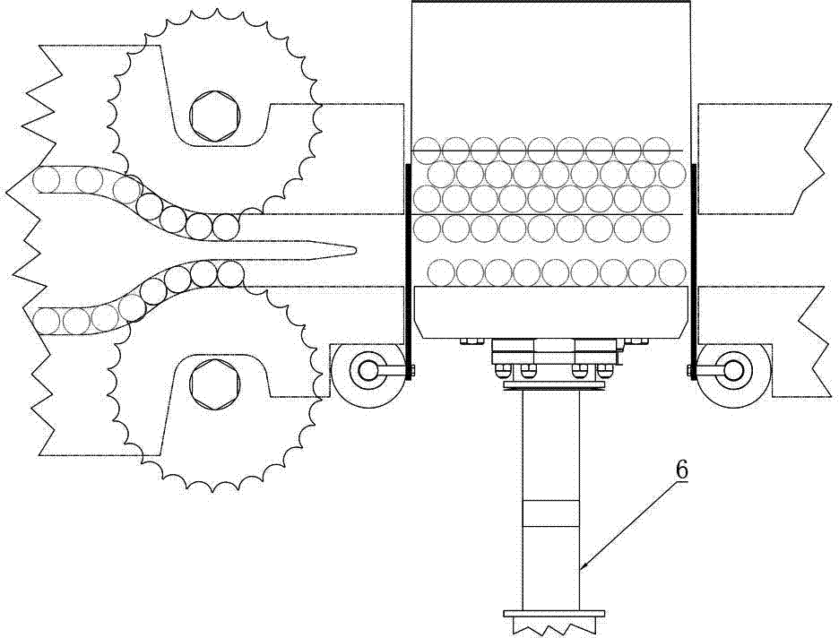
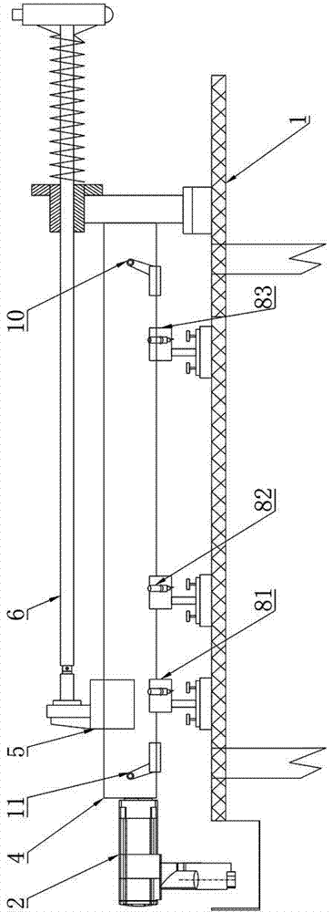
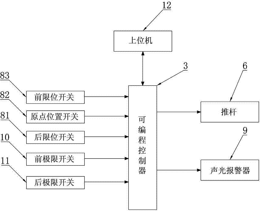
[0029] Such as Figure 1 to Figure 4 As shown, the push rod device of the freeze dryer of this embodiment for automatic feeding and discharging includes a frame 1, a push rod 6, a drive motor 2 and a control assembly. A sliding assembly is installed on the frame 1, and the sliding assembly includes a sliding platform 4. The sliding execution block 5 connected to the push rod 6 is installed on the platform 4, and the sliding execution block 5 drives the push rod 6 to perform linear telescopic movement on the sliding platform 4 under the drive of the driving motor 2, and the detection rotating shaft is installed on the rotating shaft of the driving motor 2 The detection component of the actual position is connected with the control component. The detection component detects the actual position of the rotating shaft and transmits it to the control...


PUM


Abstract

The invention discloses an automatic feeding and discharging pushing rod device of a freeze dryer. The device comprises a pushing rod, a driving motor and a control component. The pushing rod is mounted on a sliding component, and the driving motor drives the pushing rod to do linear motion on the sliding component; and a detecting component for detecting the actual position of the rotating shaft is arranged on the rotating shaft of the driving motor. The detecting component detects the actual position of the rotating shaft and transmits the actual position of the rotating shaft to the control component. The control component calculates the difference value, transmitted by the detecting component, of the actual position of the rotating shaft and the corresponding standard position, and then compares the difference value with the ideal deviation threshold value; and when the difference value is larger than the ideal deviation threshold value, a stopping command is sent to the driving motor, and therefore the pushing rod is stopped from running, and an initialized command is sent to the detecting component. The automatic feeding and discharging pushing rod device has the advantages of precisely locating the pushing rod, and preventing the pushing rod from being operated by mistakes.

Description

technical field [0001] The invention mainly relates to the field of packaging machinery for medicine, food, etc., in particular to a push rod device for automatic material feeding and discharging of a freeze dryer. Background technique [0002] The automatic loading and unloading of the freeze dryer sends the semi-stoppered vials to the shelf of the freeze dryer through the combination of the feeding integration device, the bottle unscrambling device and the feeding push rod. After the freeze-drying process cycle is completed, it is combined by the discharge push rod The integrated discharge device sends the vials out of the shelf, and transfers them to the capping machine and subsequent processes. The entire feeding and discharging process is completely controlled by the control system without manual intervention, avoiding manual contact with the product, thereby preventing the transfer process of the product to the greatest extent. The pollution caused in the environment, ...

Claims


Application Information

Patent Timeline
Patent Type & Authority Applications(China)
IPC IPC(8): B65B35/40B65B35/46B65B57/18
CPCB65B35/40B65B35/46B65B57/18
Inventor 陈双好钟元龙
Owner TRUKING TECH LTD
Why Eureka
Try Eureka