Plasma waste gasification and pyrolysis equipment

A technology of plasma and plasma torch, which is applied in the field of ion waste gasification pyrolysis equipment, can solve the problem of low energy utilization rate and achieve high energy utilization rate

Active Publication Date: 2015-07-01
SHANGHAI BOILER WORKS
View PDF8 Cites 13 Cited by
  • Summary
  • Abstract
  • Description
  • Claims
  • Application Information

AI Technical Summary

Problems solved by technology

However, the synthesis gas produced by plasma gasification needs to be rapidly cooled to...

Method used


Image

  • Plasma waste gasification and pyrolysis equipment

Examples


Embodiment

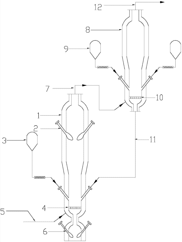
[0031] Urban waste in my country generally has high water content and low calorific value. In order to make the research of this example more universal, waste with a calorific value of 1250kcal / kg was selected for design, and the daily processing capacity was 100t / d. The invention provides a plasma garbage gasification-pyrolysis equipment, which includes two subsystems, a gasification system and a pyrolysis system, and the pyrolysis system is connected to the gasification system through circulating materials. The gasification system includes a furnace body (1) and a gasification system. Plasma torches (2), (6); by adjusting the power and quantity of the plasma torches (2), (6), the temperature of the gasification furnace (1) is 900-1300°C, and the temperature of the pyrolysis furnace is 700-900°C.

[0032] A kind of plasma waste gasification-pyrolysis equipment, it comprises the following steps:

[0033] Step 1): Domestic garbage (80t / d) enters the gasification furnace body 1 ...


PUM


Abstract

The invention discloses plasma waste gasification and pyrolysis equipment. The plasma waste gasification and pyrolysis equipment comprises a plasma waste gasification furnace, a waste pyrolysis furnace and a waste automatic feeding device; a synthesis gas outlet is formed in the top of the gasification furnace; a gasification furnace top plasma torch is arranged on the top of the gasification furnace; feeding ports of a plurality of gasification furnace cabins are formed in the middle lower part of the gasification furnace; a gasification furnace air distribution plate is arranged below the feed ports, and a gasification bottom plasma torch is arranged on the bottom of the gasification furnace; a pyrolysis synthesis gas outlet is formed in the top of the pyrolysis furnace, a feed port of the pyrolysis furnace cabin is formed in the middle lower part of the pyrolysis furnace, a pyrolysis furnace air distribution plate is arranged below the feed port. Household garbage enters the gasification furnace from the gasification furnace cabin through feed ports, gasification media enter the gasification furnace through the gasification furnace air distribution plate and carry out gasification reaction with the garbage to generate synthesis gas; the synthesis output from the top of the gasification furnace enters the pyrolysis furnace through the pyrolysis furnace air distribution plate and then carries out pyrolysis reaction with the garbage entering from the pyrolysis furnace cabin.

Description

technical field [0001] The invention relates to a plasma garbage gasification pyrolysis device. Background technique [0002] With the expansion of my country's urbanization scale, urban garbage has increased year by year, and the embarrassing situation that there is no place to bury or pile up garbage has appeared in many places. Therefore, the research and development of thermochemical treatment and conversion technology of waste is imperative. At present, the main thermochemical conversion technologies of waste in the world include waste incineration, waste pyrolysis, and waste gasification. [0003] Incineration technology obtains heat energy while achieving waste reduction, but it is the most likely to generate dioxins, and the ash requires special treatment; pyrolysis technology is the most beneficial to suppress dioxins, but requires an external heat source, and the coke produced by pyrolysis products Dioxin and ash require special treatment, and the subse...

Claims


Application Information

Patent Timeline
IPC IPC(8): C10J3/66C10B53/00B09B3/00
Inventor 程相宣倪建军李平池国镇
Owner SHANGHAI BOILER WORKS
Why Eureka
Try Eureka