Method and system for vacuuming control of ito-pvd equipment

An ITO-PVD, vacuuming technology, applied in the semiconductor field, can solve the problems of unfavorable production and processing and high equipment cost

Active Publication Date: 2017-02-08
BEIJING NAURA MICROELECTRONICS EQUIP CO LTD
View PDF4 Cites 0 Cited by
  • Summary
  • Abstract
  • Description
  • Claims
  • Application Information

AI Technical Summary

Problems solved by technology

This method has high equipment cost and is not conducive to production and processing

Method used


Image

  • Method and system for vacuuming control of ito-pvd equipment
  • Method and system for vacuuming control of ito-pvd equipment
  • Method and system for vacuuming control of ito-pvd equipment

Examples


Embodiment Construction

[0075] In order to make the purpose, technical solution and advantages of the present invention clearer, the specific implementation of the method and system for vacuuming control of ITO-PVD equipment of the present invention will be described below with reference to the accompanying drawings. It should be understood that the specific embodiments described here are only used to explain the present invention, not to limit the present invention.

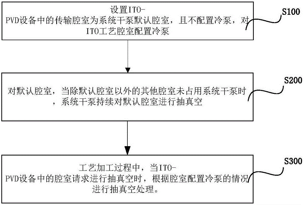
[0076] A kind of ITO-PVD equipment vacuum control method of the embodiment of the present invention, such as figure 1 shown, including the following steps:

[0077] S100, setting the transmission chamber in the ITO-PVD equipment as the default chamber of the system dry pump, and not configuring the cold pump, and configuring the cold pump for the ITO process chamber. Different from the traditional equipment configuration, the transfer chamber is not equipped with a cold pump, but the transfer chamber is set as the default chamber of t...


PUM


Abstract

The invention discloses a vacuuming control method and a system of ITO-PVD equipment, wherein the method comprises the following steps: a transmission cavity in the ITO-PVD equipment is set as a default cavity of a system dry pump, and is not allocated with a cold pump, and a cold pump is allocated for an ITO process cavity; for the default cavity, when other cavities besides the default cavity do not occupy the system dry pump, the system dry pump continuously vacuums the default cavity; and in the processing procedure, when the cavity in the ITO-PVD equipment requests for vacuuming, the vacuuming is performed according to the cold pump allocating condition of the cavity. The method saves the equipment cost and can effectively prevent the collision between hardware equipment when guaranteeing the vacuum degree requirement in the equipment processing.

Description

technical field [0001] The invention relates to the field of semiconductors, in particular to a vacuum control method for ITO-PVD equipment. Background technique [0002] Physical vapor deposition (Physical Vapor Deposition, PVD) refers to the use of low-voltage, high-current arc discharge technology under vacuum conditions, using gas discharge to evaporate the target material, and ionize both the evaporated material and the gas, and use the acceleration of the electric field The effect is to deposit the evaporated substance and its reaction product on the workpiece. This technology is widely used in IC, LED, photovoltaic, flat panel display and other fields. [0003] In recent years, due to the huge market demand for light-emitting diodes (LEDs), GaN-based LEDs have been widely used in different fields such as high-power lighting, automotive instrument displays, large-area outdoor displays, signal lights, and general lighting. Tin-doped indium oxide (IndiumTinOxide), gene...

Claims


Application Information

Patent Timeline
Patent Type & Authority Patents(China)
IPC IPC(8): C23C14/54
Inventor 张璐
Owner BEIJING NAURA MICROELECTRONICS EQUIP CO LTD
Why Eureka
Try Eureka