Self-anchoring type mounting method of suspension bridge

A self-anchored suspension bridge and installation method technology, applied in the direction of bridges, bridge construction, erection/assembly of bridges, etc., can solve the problems affecting the speed of the installation and construction of steel box girder, the threat to the safety of supports, and the rapid rise and fall of floods, so as to speed up the construction. Speed, reduce construction safety risks, and reduce the effect of investment

Active Publication Date: 2015-07-01
CHINA RAILWAY CONSTR BRIDGE ENG BUREAU GRP
View PDF8 Cites 14 Cited by
  • Summary
  • Abstract
  • Description
  • Claims
  • Application Information

AI Technical Summary

Problems solved by technology

However, the bracket method and the push-push installation scheme have the following defects: 1. The bracket method needs to set up brackets in the river, which is not allowed in many places
2. In canyon and river areas with steep bank slopes, the height difference between the bridge deck and the river bed is very large, often exceeding 100 meters. If the steel girder is installed by the bracket method, the height of the bracket in the river will exceed 100 meters, and the bracket engineering structure is huge. The cost is high; long-distance and large-tonnage jacking construction on such a high support also has a great structural safety risk, and the floods in these places rise and fall, the flow velocity is large, and there are a lot of drifting objects in the flood, which poses a threat to the safety of the support. great threat
3. In some places, due to transportation conditions, steel box girder segments cannot be directly transported to the position of the jacking platform at both ends of the bridge span. They can only be made into unit parts in the factory, and the parts are transported to the position of the jacking platform, and then pushed to the position of the jacking platform. Steel box girder sections are assembled on the platform, and the construction is pushed section by section, which seriously affects the speed of steel box girder installation and construction

Method used


Image

  • Self-anchoring type mounting method of suspension bridge
  • Self-anchoring type mounting method of suspension bridge
  • Self-anchoring type mounting method of suspension bridge

Examples


Embodiment Construction

[0030] It should be noted that, in the case of no conflict, the embodiments of the present invention and the features in the embodiments can be combined with each other.

[0031] The present invention will be described in detail below with reference to the accompanying drawings and examples.

[0032] A method for installing a self-anchored suspension bridge, comprising the steps of:

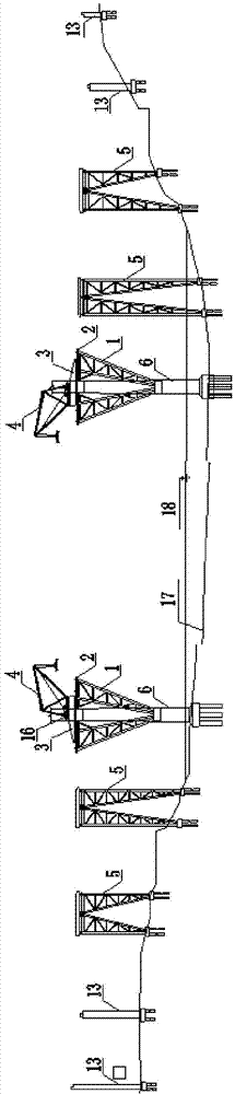
[0033] ① if figure 1 As shown, construction main tower pier 6 and main bridge side pier 13;

[0034] ② Assemble the supporting bracket 1 of the steel box girder on the main tower pier 6, and install the steel guide beam 3 on the slideway beam 2 at the top of the supporting bracket 1;

[0035] It should be noted that the supporting bracket 1 here can also serve as a side-span steel box girder pushing construction platform, which has a reliable structure and is easy to construct.

[0036] ③ Assemble the girder crane 4 on the crane base 16 on the slideway beam 2, and assemble the side-span steel ...


PUM


Abstract

The invention provides a self-anchoring type mounting method of a suspension bridge. The method comprises the steps of constructing a main pier and a side pier; erecting beams and splicing through a crane; mounting a medium supporting pier of a side span steel box beam; mounting the side span steel box beam; mounting a temporary steel tower; mounting a main span steel box beam and a temporary cable; mounting a main cable and a lifting cable; converting the systems. The method is free of the limitation of navigation of a waterway; an ultrahigh bracket cannot be constructed in the river at a gorge region with steep bank slopes, so that the input is reduced; the longitudinal moving load can be decreased, and the longitudinal moving range, so that the long-distance and large-tonnage propping and pushing can be avoided, and as a result, the risk of construction safety in longitudinal moving can be reduced; a propping pushing bracket can be avoided being scoured by flood and floating articles, so that the safety risk of construction is reduced, and the construction is sped up.

Description

technical field [0001] The invention belongs to the technical field of bridge construction, in particular to a method for installing a self-anchored suspension bridge. Background technique [0002] With the rapid development of my country's economy and society, infrastructure construction is changing with each passing day, bridge construction technology is constantly improving, and long-span self-anchored steel box girder suspension bridges are gradually increasing. The construction of a long-span self-anchored suspension bridge across rivers, lakes and seas is extremely difficult due to the influence of hydrogeological conditions. [0003] Using the existing technology to erect a long-span self-anchored suspension bridge across rivers, lakes and seas requires a large investment and high risks. The construction process of the self-anchored steel box girder suspension bridge is generally as follows: first install the steel box girder main girder, then install the main cable ...

Claims


Application Information

Patent Timeline
Patent Type & Authority Applications(China)
IPC IPC(8): E01D21/00
Inventor 陈宁贤石九州朱永胜常洁蔡文涛邢如祥张庆
Owner CHINA RAILWAY CONSTR BRIDGE ENG BUREAU GRP
Why Eureka
Try Eureka