Oil tank for hydraulic mechanism

A hydraulic mechanism and oil tank technology, applied in the field of hydraulic systems, can solve problems such as unfavorable hydraulic mechanism normal power, affecting oil flow and heat dissipation effect, insufficient oil heat dissipation distance, etc., achieving good application prospects, ensuring normal power output, The effect of simple structure

Inactive Publication Date: 2015-07-01
SUZHOU JINXIN CONSTR GRP
View PDF3 Cites 8 Cited by
  • Summary
  • Abstract
  • Description
  • Claims
  • Application Information

AI Technical Summary

Problems solved by technology

[0003] The technical problem solved by the present invention is that in the oil tank of the existing hydraulic mechanism, the oil circulation distance before the oil inlet pipe and the oil outlet pipe is relatively short, resulting in insufficient heat dissipation distance of the oil liquid, and the oil temperature at the oil outlet pipe is too high, which is not conducive to the normal operation of the hydraulic mechanism. power output, and the bottom surface of the fuel tank is a flat design, which affects the flow and heat dissipation of the oil

Method used


Image

  • Oil tank for hydraulic mechanism

Examples


Embodiment Construction

[0015] The present invention will be further described below in conjunction with the accompanying drawings.

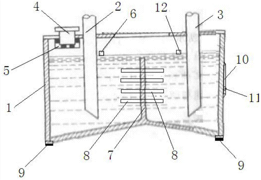
[0016] Such as figure 1 As shown, a fuel tank for a hydraulic mechanism is characterized in that it includes a fuel tank body 1, and the bottom of the fuel tank body 1 is in a concave isosceles triangle shape, which can increase the flow tendency of liquid oil. There are oil inlet pipe 2 and oil outlet pipe 3 arranged in parallel, the upper part of oil inlet pipe 2 and oil outlet pipe 3 extends out of the upper surface of oil tank body 1, oil inlet pipe 2 is connected with the oil outlet end of the hydraulic mechanism, and oil outlet pipe 3 is connected with the oil outlet of the hydraulic mechanism. The oil inlet ends are connected, and the upper surface of the fuel tank body 1 is provided with a ventilating filling port 4, and the end of the venting filling port located in the fuel tank body 1 is provided with a filter screen 5, and the fuel tank body 1 is also provi...


PUM


Abstract

The invention discloses an oil tank for a hydraulic mechanism. The oil tank comprises an oil tank body; the bottom of the oil tank body is in a concave isosceles triangle shape; an oil inlet pipe and an oil outlet pipe are arranged in parallel in the oil tank body; the upper parts of the oil inlet pipe and the oil outlet pipe extend out of the upper surface of the oil tank body; the oil inlet pipe is connected with the oil outlet end of the hydraulic mechanism, while the oil outlet pipe is connected with the oil inlet end of the hydraulic mechanism; a ventilating oil filler is arranged on the upper surface of the oil tank body and a filter screen is arranged at one end, located inside the oil tank body, of the ventilating oil filler; a liquid level sensor is further arranged in the oil tank body; a separator is located at the bottom of the oil tank body and between the oil inlet pipe and the oil outlet pipe; cooling fins are distributed at intervals on the two sides of the separator. The oil tank for the hydraulic mechanism is capable of increasing the flowing tendency of the liquid oil; the separator is arranged between the oil inlet pipe and the oil outlet pipe, so that the cooling distance of the liquid oil can be increased, the normal oil temperature at the oil outlet pipe can be guaranteed and the normal power output of the hydraulic mechanism is guaranteed; the oil tank for the hydraulic mechanism is simple in structure and easy to implement, and has excellent application prospect.

Description

technical field [0001] The invention relates to an oil tank for a hydraulic mechanism, belonging to the technical field of hydraulic systems. Background technique [0002] The hydraulic mechanism can provide powerful power and is widely used in construction machinery. The oil tank of the hydraulic mechanism is used to store oil, dissipate heat, and separate impurities and air in the oil. It is a key component of the hydraulic mechanism and is directly related to the performance of the hydraulic mechanism. At present, in the oil tank of the hydraulic mechanism, the oil circulation distance before the oil inlet pipe and the oil outlet pipe is relatively short, resulting in insufficient heat dissipation distance of the oil, and the oil temperature at the oil outlet pipe is too high, which is not conducive to the normal power output of the hydraulic mechanism. The bottom surface is a flat design, which affects the flow and heat dissipation of the oil. Contents of the invention...

Claims


Application Information

Patent Timeline
Patent Type & Authority Applications(China)
IPC IPC(8): F15B1/26F15B21/04
CPCF15B1/26F15B21/042
Inventor 薛炳泉胡斌徐军
Owner SUZHOU JINXIN CONSTR GRP
Why Eureka
Try Eureka