Oil pan assembly

An oil pan and assembly technology, applied in the field of crankcases, can solve the problems of oil emulsification, the time interval between engine start and stop is short, and the oil cannot be fully heated, etc., so as to prolong the service life and ensure the effect of normal power output.

Active Publication Date: 2020-04-24
NINGBO GEELY ROYAL ENGINE COMPONENTS +1
View PDF13 Cites 3 Cited by
  • Summary
  • Abstract
  • Description
  • Claims
  • Application Information

AI Technical Summary

Problems solved by technology

[0004] When the above-mentioned engine is running, the above-mentioned crankcase ventilation system can work normally. When the engine is turned off, the crankcase ventilation system will stop working. Therefore, when the working environment of the engine is below zero and the vehicle is moved for a short distance, the engine’s The time interval between starting and stopping is short, the electric heating device cannot fully heat the oil in the oil pan, and the water in the oil in the oil pan will not evaporate to form water vapor, even if the electric heating device continues to work after the engine is turned off, it will The oil in the oil pan is heated to evaporate the water in the oil to form water vapor. The water vapor is located in the crankcase. Since the crankcase ventilation system does not work when the engine is turned off, the water vapor in the crankcase cannot be discharged. The water vapor It remains in the crankcase all the time, and when the engine oil cools down, the water vapor liquefies to form water droplets and mixes with the engine oil, which cannot solve the problem of emulsification or freezing of the engine oil during short-distance maneuvering

Method used


Image

  • Oil pan assembly
  • Oil pan assembly
  • Oil pan assembly

Examples


Embodiment Construction

[0038] The following are specific embodiments of the present invention and in conjunction with the accompanying drawings, the technical solutions of the present invention are further described, but the present invention is not limited to these embodiments.

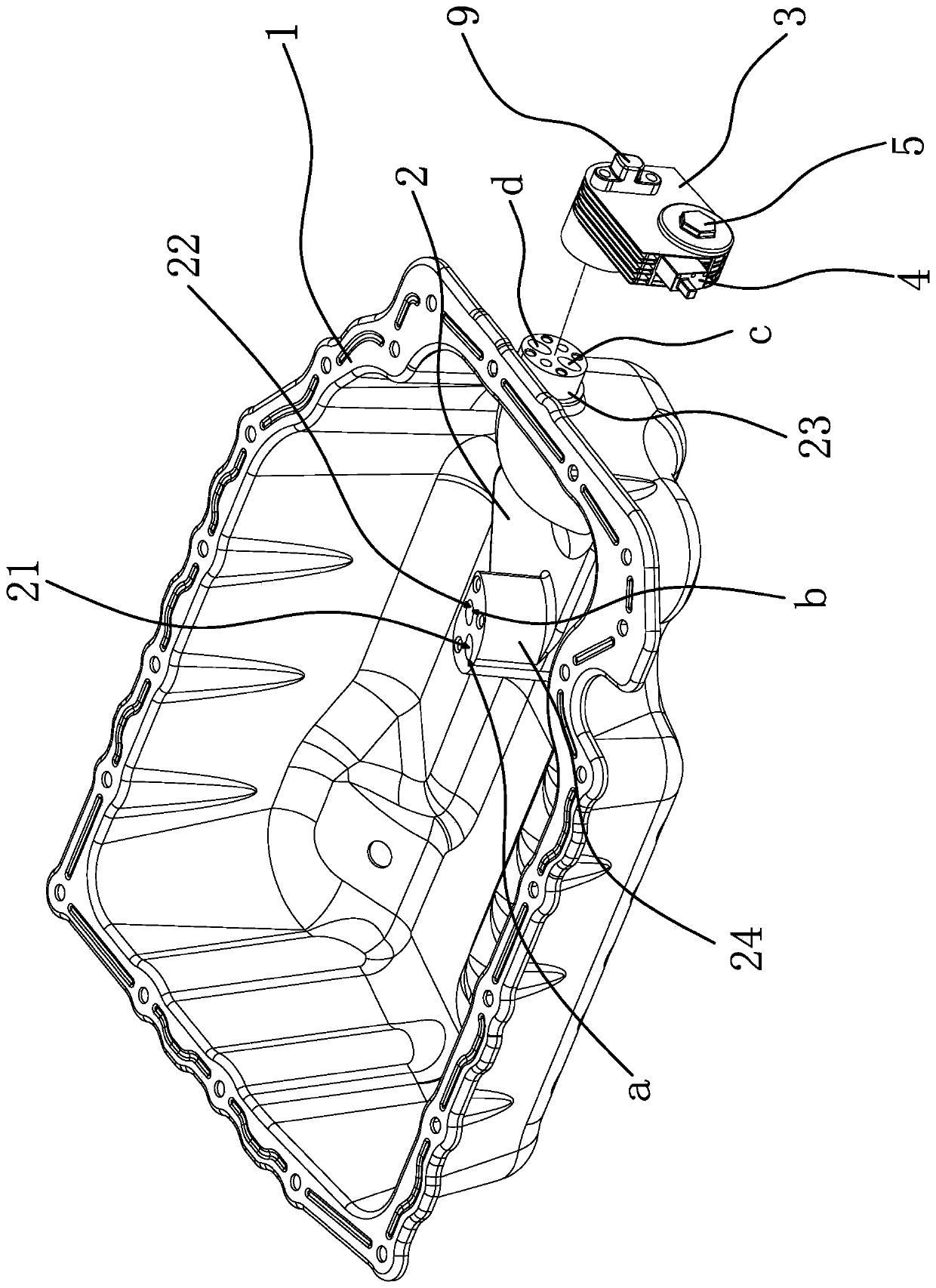
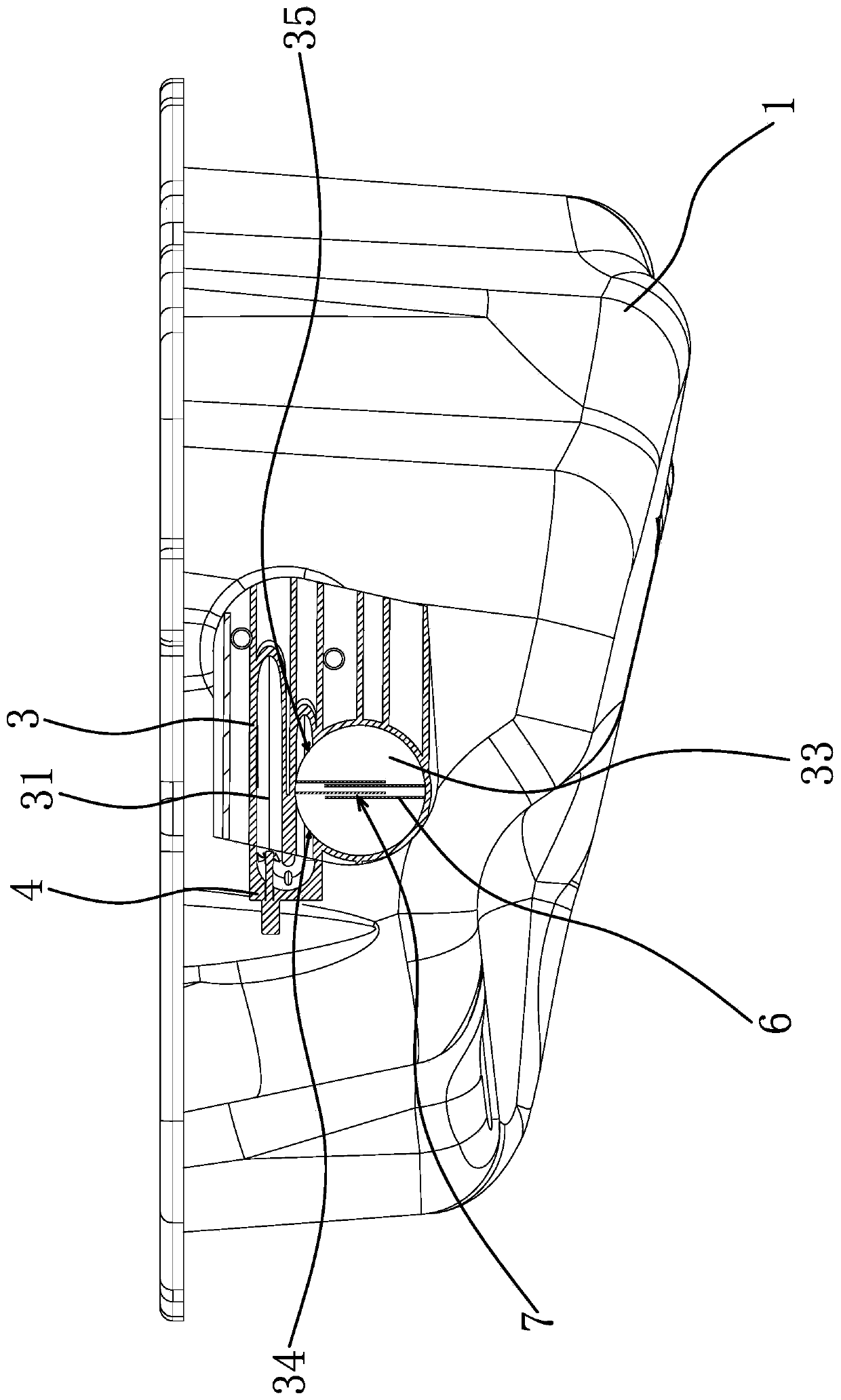
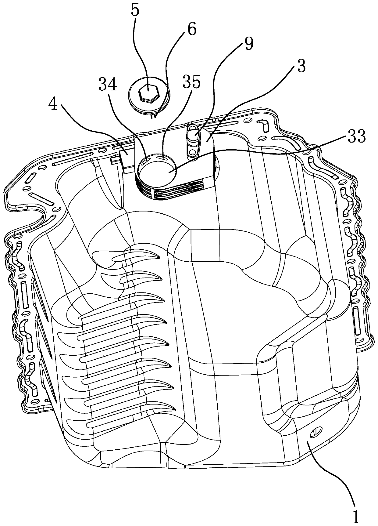
[0039] Such as figure 1 , figure 2 with Figure 5 As shown, the oil pan assembly includes an oil pan 1 and an electric heating block 2 at least partly arranged in the oil pan 1. The electric heating block 2 has an extension part 23 pierced on the oil pan 1, extending The outer end of the part 23 is located outside the oil pan 1, and the inside of the electric heating block 2 has an air intake channel 21 and an air outlet channel 22, the air inlet a of the air intake channel and the exhaust port b of the air outlet channel are located in the oil pan 1, Both the exhaust port c of the air intake channel and the air intake port d of the air outlet channel are located on the extension part 23. The oil pan 1 assembly also inc...


PUM


Abstract

The invention provides an oil pan assembly, and belongs to the technical field of oil pans. The oil pan assembly solves the problem that water in engine oil can not be removed in the short-distance starting and stopping process of an existing vehicle. The oil pan assembly comprises an oil pan and an electric heating block at least partially arranged in the oil pan, wherein the electric heating block is internally provided with a gas inlet channel and a gas outlet channel, and a gas inlet of the gas inlet channel and a gas outlet of the gas outlet channel are both positioned in the oil pan; andthe oil pan assembly also comprises a crankcase ventilation shell positioned outside the oil pan, wherein a condensation channel is arranged in the crankcase ventilation shell, one end of the condensation channel is in communication with the gas inlet channel, the other end of the condensation channel is in communication with the gas outlet channel, and an electric gas sucking pump communicatingwith the condensation channel is arranged on the crankcase ventilation shell. The oil pan assembly can remove the water in the engine oil in the short-distance starting and stopping process of the vehicle.

Description

technical field [0001] The invention belongs to the technical field of crankcases and relates to an oil pan assembly. Background technique [0002] When the engine is working, there is a high-pressure combustible mixture and burned gas in the combustion chamber. These gases will more or less enter the crankcase through the gap between the piston group and the cylinder, and the gas that enters the crankcase is composed of water vapor. , exhaust gas and unburned fuel gas, etc., when the engine oil in the oil pan is at a low temperature, the water vapor liquefies and mixes with the engine oil, resulting in the dilution of the engine oil, resulting in emulsification of the engine oil and reducing the performance of the engine oil. It also accelerates the oxidation and deterioration of the oil. In addition, when the engine is used in a particularly cold environment, the water mixed in the oil will condense into ice cubes, causing serious problems such as blockage of the oil pump...

Claims


Application Information

Patent Timeline
Patent Type & Authority Applications(China)
IPC IPC(8): F01M11/00F01M11/03B01D1/00B01D1/30
CPCB01D1/0017B01D1/30F01M11/0004F01M11/03
Inventor 王文武魏丽娜姚君韦刘东赵福成王瑞平
Owner NINGBO GEELY ROYAL ENGINE COMPONENTS
Why Eureka
Try Eureka