Automatic measurement and classification method and system of steel dimple image depth uniformity
A technology for automatic measurement and image depth, used in instruments, character and pattern recognition, computer parts, etc., and can solve problems such as low accuracy and low efficiency
- Summary
- Abstract
- Description
- Claims
- Application Information
AI Technical Summary
Problems solved by technology
Method used
Image
Examples
Embodiment 1
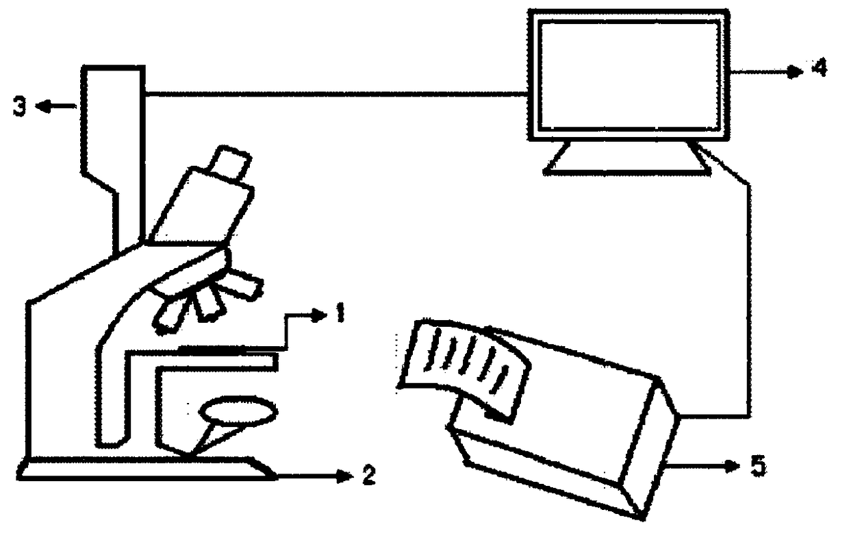
[0107] Use the image acquisition device to obtain the original image of the steel dimple to be tested. The hardware of the image acquisition device is as follows: figure 2 Shown: a steel sample 1, a scanning electron microscope 2, a camera 3, a computer 4 and a printer 5, and the computer 4 is attached with an image acquisition card.
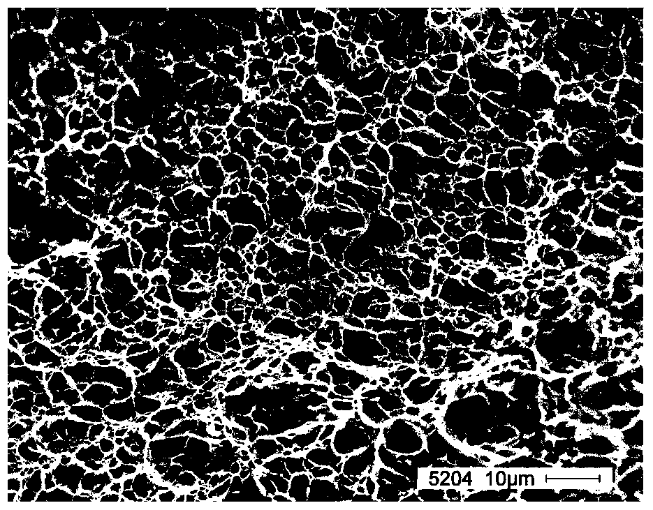
[0108] The specific steps of image acquisition are to use the scanning electron microscope 2 to adjust the image to a suitable focal length, and use the camera 3 to take pictures when the original image of the steel dimple to be tested is the clearest and store it in the image acquisition card in the computer 4 , the original image of the steel dimple to be tested in steel sample 1 is obtained (such as image 3 shown), followed by subsequent image preprocessing.
[0109] The process of image preprocessing includes: median filter denoising, binary segmentation and dimple defect boundary repair.
[0110] Median filter denoising: first use the m...
Embodiment 2
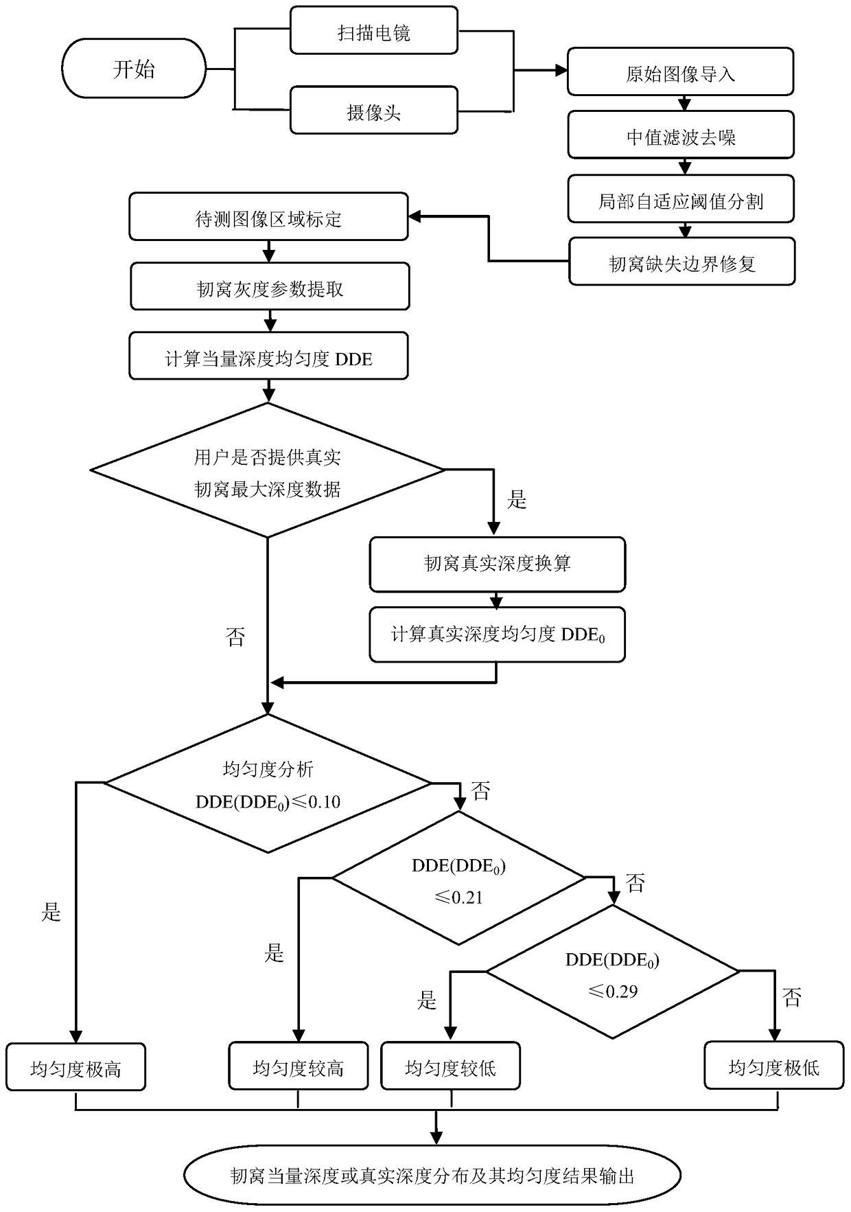
[0168] Figure 10 is the original image of the dimple to be tested in steel sample 2. The processing process of the present invention is as follows: first, the original image of the target dimple to be measured is subjected to median filtering and denoising, and the image after median filtering and denoising is as follows: Figure 11 As shown; the filtered image is processed by a local adaptive threshold segmentation algorithm, and the image after binary segmentation is as follows Figure 12 shown in Fig. 1; and then use the limit corrosion controlled by the quenching function method and the layer-by-layer expansion method to repair the missing boundary of the dimple. The image after the boundary repair is as follows Figure 13 Shown; area calibration is performed on the image to be tested, and the image after area calibration is traversed and scanned to extract the gray extreme value of each dimple area in the dimple image, and at the same time calculate the dimple equivalen...
Embodiment 3
[0170] Figure 15 is the original image of the dimple to be tested in steel sample 3. Now use the present invention to its processing process: first carry out median filtering denoising to target image, the image after median filtering denoising is as follows Figure 16 As shown; the filtered image is processed by a local adaptive threshold segmentation algorithm, and the image after binary segmentation is as follows Figure 17 shown in Fig. 1; and then use the limit corrosion controlled by the quenching function method and the layer-by-layer expansion method to repair the missing boundary of the dimple. The image after the boundary repair is as follows Figure 18 Shown; area calibration is performed on the image to be tested, and the image after area calibration is traversed and scanned to extract the gray extreme value of each dimple area in the dimple image, and at the same time calculate the dimple equivalent depth uniformity DDE (not specified by the user can provide th...
PUM
| Property | Measurement | Unit |
|---|---|---|
| Depth | aaaaa | aaaaa |
Abstract
Description
Claims
Application Information
 - R&D
- Intellectual Property
- Life Sciences
- Materials
- Tech Scout
- Unparalleled Data Quality
- Higher Quality Content
- 60% Fewer Hallucinations
Browse by: Latest US Patents, China's latest patents, Technical Efficacy Thesaurus, Application Domain, Technology Topic, Popular Technical Reports.
© 2025 PatSnap. All rights reserved.Legal|Privacy policy|Modern Slavery Act Transparency Statement|Sitemap|About US| Contact US: help@patsnap.com


