
Object-oriented building change detection method based on multi-feature fusion

A multi-feature fusion and object-oriented technology, applied in image analysis, instrumentation, computing, etc., can solve problems such as relying on the results of feature extraction, ignoring differences, and difficult target extraction

Active Publication Date: 2015-07-01
WUHAN UNIV
View PDF3 Cites 37 Cited by
  • Summary
  • Abstract
  • Description
  • Claims
  • Application Information

AI Technical Summary

Problems solved by technology

Cell-level change detection maintains as much original information as possible, and has detailed information that is not available at the feature level and target level. However, pixel-level change detection only considers changes in pixel attributes, without considering its spatial and other feature attributes. change; feature-level change detection not only takes into account the change of spatial shape, but also considers the change of feature attributes, but feature-level change detection depends on the result of feature extraction, and using a certain feature alone for change detection may cause great damage. Missed detection and false detection; the biggest advantage of target-level change detection is that it is close to the needs of users, and the detection results can be directly applied. Its shortcoming lies in the difficulty of target extraction
The simple single-band subtraction does not consider the statistical correlation between the bands, so that the subtraction of values ​​​​with different absolute values ​​​​gets the same size difference, and the comparison between different pixel gray values ​​​​gets the same size ratio, ignoring the difference. Differences in ground features in different sensitive bands lead to loss of potentially usable information

Method used


Image

  • Object-oriented building change detection method based on multi-feature fusion
  • Object-oriented building change detection method based on multi-feature fusion
  • Object-oriented building change detection method based on multi-feature fusion

Examples


Embodiment Construction

[0052] In order to facilitate those of ordinary skill in the art to understand and implement the present invention, the present invention will be described in further detail below in conjunction with the accompanying drawings and embodiments. It should be understood that the implementation examples described here are only used to illustrate and explain the present invention, and are not intended to limit this invention.

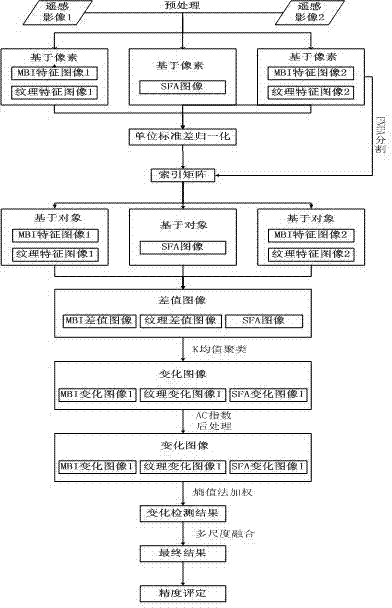
[0053] please see figure 1 A kind of object-oriented building change detection method based on multi-feature fusion provided by the invention comprises the following steps:

[0054] Step 1: Preprocessing two high-resolution remote sensing images A and B in different phases of the selected area, mainly including geometric correction, radiation correction, geometric registration and image cropping;

[0055] (1) Geometric correction: the geometric correction method of the present invention adopts geometric correction of remote sensing images based on polynomial...


PUM


Abstract

The invention discloses an object-oriented building change detection method based on multi-feature fusion. The method includes: solving MBIs (morphological building indexes), texture features and SFA (slow feature analysis) graphs of image pixels; performing FNEA (fractal net evolution approach) splitting through the MBIs and the texture features; solving three feature values of each object, performing differencing, and solving a threshold by a K-means clustering algorithm to obtain a feature change graph; performing post-processing through AC indexes; solving weights of different feature change graphs by an entropy method, and setting thresholds according to the weights to obtain change images; performing post-processing by a voting method to obtain change detection results. The method has the advantages that building changes are detected through the MBIs, the SFA graphs and the texture features, the MBIs and the texture features are added to the FNEA splitting, the AC indexes are provided, and post-processing is performed by the voting method. A novel way for the application of high-resolution remote sensing images, land coverage and urban expansion is provided.

Description

technical field [0001] The invention belongs to the technical field of information extraction of remote sensing image data, and in particular relates to an object-oriented building change detection method based on multi-feature fusion. Background technique [0002] With the acceleration of economic development and urbanization, various production and construction activities of human beings are increasingly changing the natural environment and land cover types in and around cities. Therefore, it is of great significance to the sustainable development of our country to quickly and effectively monitor these change information and analyze the cause and effect of the change. The remote sensing image change detection technology is a technology to obtain the changes of surface features based on two remote sensing images in different phases of the same area. The rapid development of this technology plays an important role in updating geospatial data. Remote sensing change detection...

Claims


Application Information

Patent Timeline
IPC IPC(8): G06T7/00
Inventor 邵振峰陶峰
Owner WUHAN UNIV
Learn More