Supercharge Your Innovation With Domain-Expert AI Agents!

Reading operation time control circuit

一种时间控制电路、读操作的技术,应用在只读存储器、数字存储器信息、仪器等方向,能够解决时间控制信号无法改变、无法满足不同待测器件需求等问题,达到降低平均读功耗的效果

Active Publication Date: 2015-07-01
SHANGHAI HUAHONG GRACE SEMICON MFG CORP
View PDF3 Cites 1 Cited by
  • Summary
  • Abstract
  • Description
  • Claims
  • Application Information

AI Technical Summary

Problems solved by technology

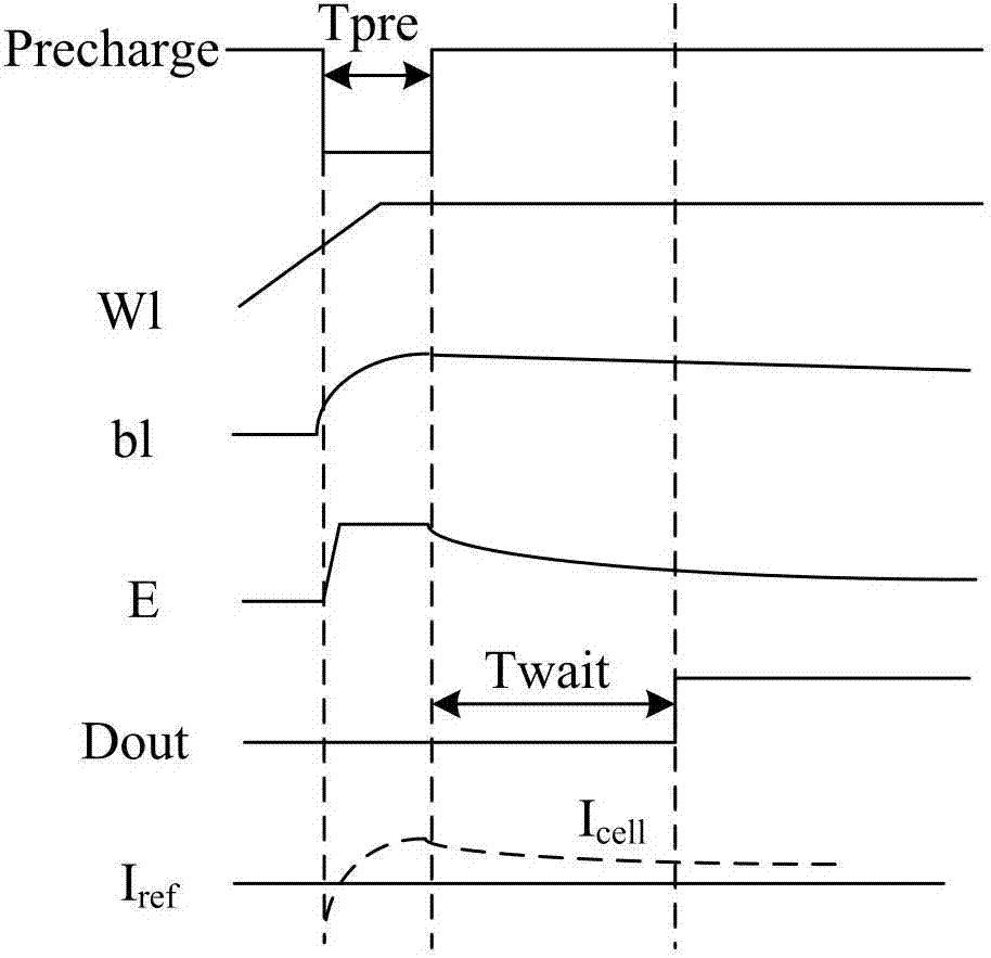
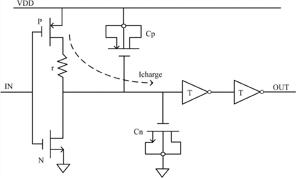
However, since the R and C of the RC delay circuit are fixed during the preparation, the time control signals Tpre and Twait generated by it cannot be changed, which cannot meet the needs of different devices under test.

Method used


Image

  • Reading operation time control circuit
  • Reading operation time control circuit
  • Reading operation time control circuit

Examples


Embodiment Construction

[0023] The read operation time control circuit of the present invention will be described in more detail below in conjunction with the schematic diagram, wherein a preferred embodiment of the present invention is represented, it should be understood that those skilled in the art can modify the present invention described here, and still realize the advantages of the present invention Effect. Therefore, the following description should be understood as the broad knowledge of those skilled in the art, but not as a limitation of the present invention.

[0024] In the interest of clarity, not all features of an actual implementation are described. In the following description, well-known functions and constructions are not described in detail since they would obscure the invention with unnecessary detail. It should be appreciated that in the development of any actual embodiment, numerous implementation details must be worked out to achieve the developer's specific goals, such as ...


PUM


Abstract

The invention provides a reading operation time control circuit. A virtual device circuit and a virtual sensitivity amplifying circuit are added, the current of a reference device circuit is imaged to the virtual device circuit by a current mirror, and the virtual sensitivity amplifying circuit generates a time control signal according to the current of the virtual device circuit; as the current of the virtual device circuit is the same as the current of the reference device, and also can be changed along with the change of the size of the device, the virtual sensitivity amplifying circuit is ensured to be changed correspondingly along with the change of the size of the device according to the time control signal formed by the current, a disadvantage that the time control signal is fixed after the RC (resistance-capacitance) delay circuit is prepared in the prior art is overcome, the virtual sensitivity amplifying circuit can be changed along with the change of the device size and the PVT (pressure-volume-temperature), and the average reading power consumption is reduced effectively.

Description

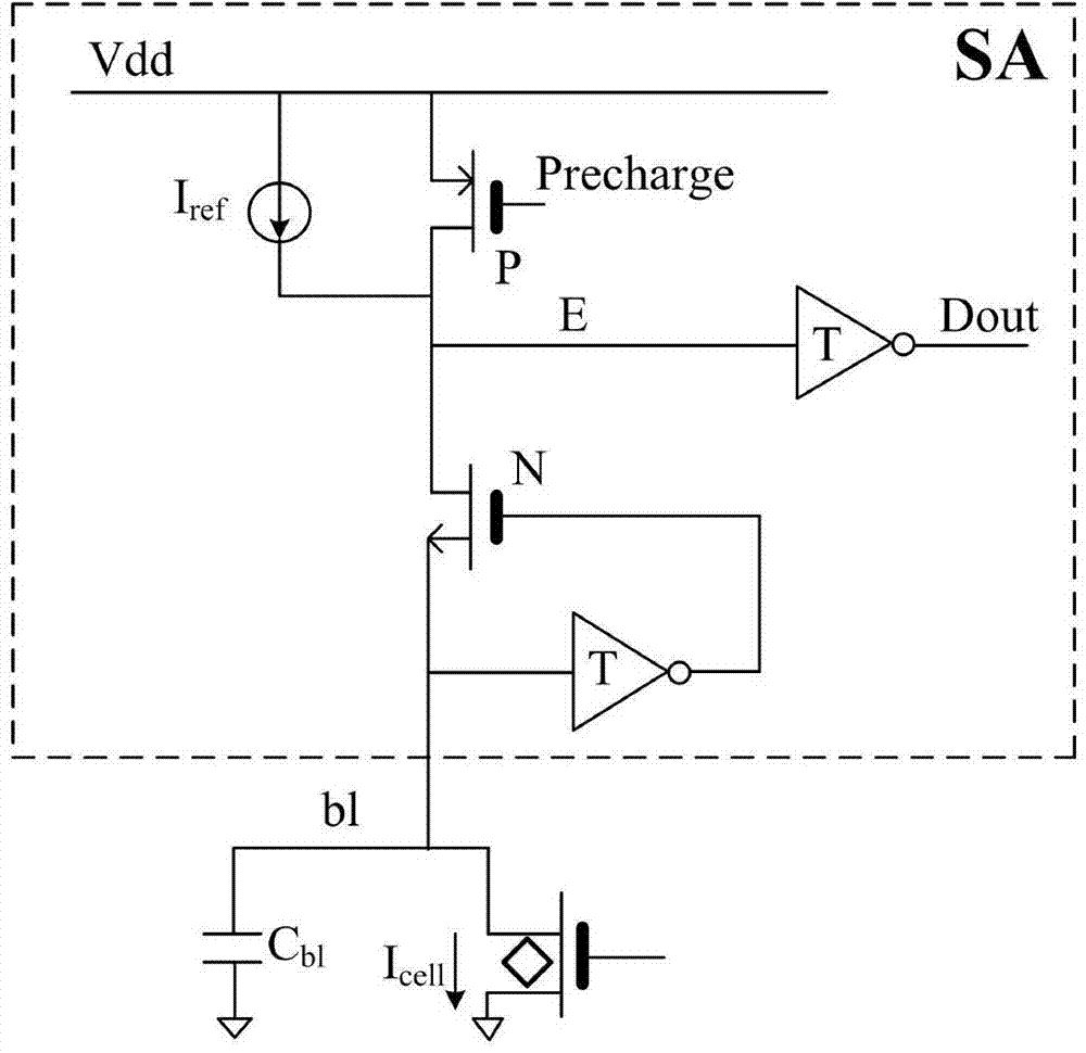
technical field [0001] The invention relates to the field of semiconductor manufacturing, in particular to a read operation time control circuit. Background technique [0002] When performing a read operation on a flash memory (Flash), a signal generation circuit is usually required to generate a time control signal (Control signal) so as to read data in one read cycle. In the prior art, an RC delay circuit (RC delay circuit) is usually used to generate a time control signal for charging and discharging. [0003] Specifically, please refer to figure 1 , figure 1 It is a schematic diagram of the circuit structure of the sensor amplifier circuit (SA) in the prior art; wherein, the sensor amplifier circuit includes a PMOS transistor (P), an NMOS transistor (N) and two inverters, and the drain of the PMOS transistor The pole is connected to an inverter input, and the output of the inverter is a data output terminal (Dout), and the gate of the PMOS transistor is connected to t...

Claims


Application Information

Patent Timeline
Patent Type & Authority Applications(China)
IPC IPC(8): G11C16/26
CPCG11C7/08G11C7/227G11C16/0483G11C16/26G11C16/32G11C29/023G11C29/026G11C29/24G11C29/50012G11C7/06G11C7/14G11C8/10G11C7/1051
Inventor 张勇肖军
Owner SHANGHAI HUAHONG GRACE SEMICON MFG CORP
Features
  • R&D
  • Intellectual Property
  • Life Sciences
  • Materials
  • Tech Scout
  • Unparalleled Data Quality
  • Higher Quality Content
  • 60% Fewer Hallucinations
Learn More