Method used for prediction convergence control of inductive current in booster circuit

A technology of inductive current and boost circuit, applied in control/regulation systems, electrical components, regulating electrical variables, etc., can solve problems such as large static error, slow dynamic response characteristics, and poor control accuracy

Inactive Publication Date: 2015-07-01
XIAN UNIV OF TECH
View PDF4 Cites 8 Cited by
  • Summary
  • Abstract
  • Description
  • Claims
  • Application Information

AI Technical Summary

Problems solved by technology

[0004] The purpose of the present invention is to provide a method for predictive convergence control of inductor current in a boost circuit, which solves the problems of slow dynamic response characteristics, large static difference and poor control accuracy in the prior art

Method used


Image

  • Method used for prediction convergence control of inductive current in booster circuit
  • Method used for prediction convergence control of inductive current in booster circuit
  • Method used for prediction convergence control of inductive current in booster circuit

Examples


Embodiment Construction

[0078] The present invention will be described in detail below in conjunction with the accompanying drawings and specific embodiments.

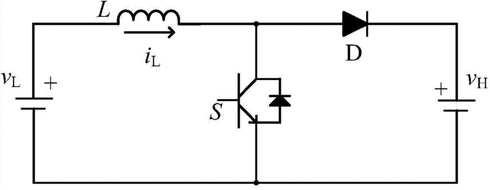
[0079] Such as figure 1 Shown is the boost (Boost) circuit diagram of the present invention, and the Boost circuit includes a low-voltage voltage source v L (The low-voltage voltage source is generally a device capable of storing energy such as a supercapacitor or a battery), and the low-voltage voltage source v L The negative pole of the high voltage voltage source v H (Generally, it is the voltage of the supporting capacitor connected in parallel with the DC bus. Since the capacitor voltage cannot change abruptly, it can be regarded as a voltage source in a short time). , The anode of the diode D is connected, and the cathode of the diode D is connected to the high-voltage voltage source v H positive connection.

[0080] The switching tube S is a turn-off power switching device carrying an anti-parallel diode or having the characteristi...


PUM


Abstract

The invention discloses a method used for prediction convergence control of inductive current in a booster circuit. The method includes: predicting an inductive current value of a next moment through an inductive current value iL(n-1) of a previous moment; predicting to acquire a value of a duty ratio of a switch tube at an nTS time moment according to power conservation; subjecting a calculation result to convergence processing according to a steady-state expected value; predicting to acquire an average value of the duty ratio of the switch tube and the duty ratio of the switch tube in a steady state in the process of convergence so as to acquire a final duty ratio Dx(n) of the switch tube and generate PWM (pulse width modulation) with the duty ratio of Dx(n) to control the switch tube to realize control on inductive current. By the method, the duty ratio of the switch tube is calculated quickly by taking the inductive current as controlled amount; when a given is suddenly increased or reduced, the given can be tracked quickly, so that an algorithm can acquire good dynamic-steady state characteristics.

Description

technical field [0001] The invention belongs to the technical field of power electronic circuit control, and in particular relates to a predictive convergence control method for inductive current in a boost circuit. Background technique [0002] In recent years, a boost (Boost) converter is a widely used power electronic switching circuit, which is often used in equipment for DC power transmission. The output voltage or output current of the circuit is usually controlled by adjusting the modulation duty ratio of the power tube in the circuit. The input side of the boost circuit is usually a photovoltaic array, battery, super capacitor or other power supply. By controlling and regulating the converter, it can Output electric energy to the load according to the given value. [0003] Nowadays, there are many control methods for Boost converters, such as PI control, repetitive control, fuzzy control, and sliding film control. Repeated control has the advantages of high control...

Claims


Application Information

Patent Timeline
Patent Type & Authority Applications(China)
IPC IPC(8): H02M3/156
Inventor 张琦刘昭孙向东安少亮任碧莹杨惠赵双双
Owner XIAN UNIV OF TECH
Why Eureka
Try Eureka