PWM rectifier control method with uncontrolled inductance current minimum phase

A technology of inductive current and control method, which is applied in the direction of converting AC power input to DC power output, electrical components, output power conversion devices, etc., and can solve problems such as low efficiency, switching loss, and large PWM rectifier loss

Inactive Publication Date: 2015-07-01
SOUTH CHINA UNIV OF TECH
View PDF8 Cites 0 Cited by
  • Summary
  • Abstract
  • Description
  • Claims
  • Application Information

AI Technical Summary

Problems solved by technology

However, the switching state needs to be switched frequently during the working process of the PWM rectifier. When the switching tube is turned on and off, the voltage and current are not zero, so there are switching losses d

Method used


Image

  • PWM rectifier control method with uncontrolled inductance current minimum phase
  • PWM rectifier control method with uncontrolled inductance current minimum phase
  • PWM rectifier control method with uncontrolled inductance current minimum phase

Examples


Embodiment Construction

[0051] The present invention will be further described in detail below in conjunction with the embodiments and the accompanying drawings, but the embodiments of the present invention are not limited thereto.

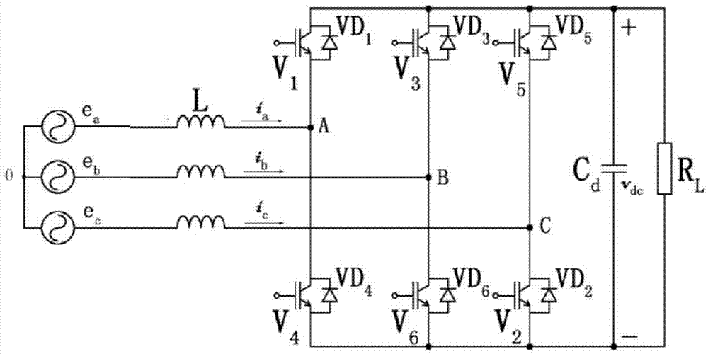
[0052] figure 1 is the PWM rectifier circuit topology, the first switch V 1 and the first diode VD 1 anti-parallel connection, the second switch V 2 and the second diode VD 2 Anti-parallel connection, the third switching tube V 3 and the third diode VD 3 anti-parallel connection, the fourth switching tube V 4 and the fourth diode VD 4 anti-parallel connection, the fifth switching tube V 5 and fifth diode VD 5 Anti-parallel connection, the sixth switch V 6 and the sixth diode VD 6 Anti-parallel connection, the two components in anti-parallel connection are parallel but conduction direction is opposite, the first diode VD 1 , the third diode VD 3 , the fifth diode VD 5 The cathodes of the second diode VD are connected in parallel together 2 , the fourth diode...


PUM


Abstract

The invention discloses a PWM rectifier control method with uncontrolled inductance current minimum phase. The method includes sampling the three phase currents ia, ib and ic of a, b and c of a PWM rectifier, comparing the three phase currents ia, ib and ic, and determining the minimum current; according to a spatial voltage vector command value V*, determining the sections, where the spatial voltage vector command value V* located, of a complex plane; according to the different sections of the complex plane of the spatial voltage vector command value V*, composing the spatial voltage vector command value V* through different basic vectors; determining the actions of switch tubes, and avoiding controlling the minimum phase of the inductance current of the PWM rectifier. According to the control method, the switch consumption of the PWM rectifier is reduced, the efficiency of the PWM rectifier is improved, the higher sampling frequency can be provided to the PWM rectifier during operation, and the high frequency and lightness of the PWM rectifier can be realized.

Description

technical field [0001] The invention relates to the technical field of power electronics applications, in particular to a control method for a PWM rectifier in which the minimum phase of the inductance current is not controlled. Background technique [0002] The voltage source PWM rectifier has been widely used due to its advantages of high controllability, high power factor, low harmonic content and high efficiency. However, the switching state of the PWM rectifier needs to be switched frequently during the working process. During the process of turning on and off the switching tube, the voltage and current are not zero, so there are switching losses during the switching process of the switching state. The switching loss is directly proportional to the switching frequency. The more switching times per unit time, the greater the loss of the PWM rectifier and the lower the efficiency. Reducing the number of switching states can reduce the switching loss of the PWM rectifier ...

Claims


Application Information

Patent Timeline
IPC IPC(8): H02M7/219
Inventor 康龙云冯自成陈凌宇
Owner SOUTH CHINA UNIV OF TECH
Why Eureka
Try Eureka