High-voltage large-current electronic switch

An electronic switch, high current technology, applied in electronic switches, electrical components, pulse technology and other directions, can solve problems such as difficulty, cumbersome process, cumbersome and other problems, achieve the effect of reducing cumbersome and difficult, solving poor linearity, and simple principle

Pending Publication Date: 2015-07-01
SHANGHAI PRIMA ELECTRONICS
View PDF12 Cites 0 Cited by
  • Summary
  • Abstract
  • Description
  • Claims
  • Application Information

AI Technical Summary

Problems solved by technology

Finally, through a small switch circuit, 400VDC is sent to the wire passing through the coil in the form of a pulse, and finally the driving voltage is induced on the coil to drive the conduction of the IGBT tube. It is complex, and has higher requirements for the small switch used to drive 400VDC into a pulse at the end. The response speed must be fast, and the power requirement is also high.
For the existing high-pressure processing module, the manufacturing process is very cumbersome and difficult. The cumbersome and difficult process can easily lead to poor performance of the product, and even directly cause the switch to be directly damaged.
Another fatal shortcoming of the existing high-voltage and high-current electronic switches is that the linearity of the front edge of the pulse waveform passing through the switch is poor.
[0003] For the thyristor control module, the existing method is to drive a thyristor with a magnetic ring. We know that high-voltage and high-current electronic switches generally consist of one hundred to several hundred thyristors. It is conceivable that the module manufacturing process of the existing method is very difficult complicated

Method used


Image

  • High-voltage large-current electronic switch
  • High-voltage large-current electronic switch

Examples


Embodiment Construction

[0017] The present invention will be described in detail below in conjunction with the accompanying drawings and specific embodiments. This embodiment is carried out on the premise of the technical solution of the present invention, and detailed implementation and specific operation process are given, but the protection scope of the present invention is not limited to the following embodiments.

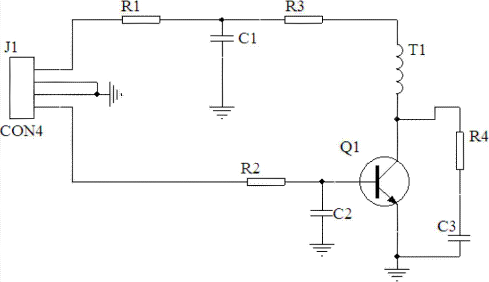
[0018] A high-voltage high-current electronic switch, including a drive circuit module, a high-voltage processing module, and a thyristor control module connected in sequence, such as figure 1 As shown, the drive circuit module includes a plug J1, a triode circuit, a coil wire T1 and a DC auxiliary energy storage circuit, the plug J1 is respectively connected to the triode circuit and the DC auxiliary energy storage circuit, and the triode circuit, the wiring The coil wire T1 and the DC auxiliary energy storage circuit are sequentially connected.

[0019] The DC auxiliary energy stor...


PUM


Abstract

The invention relates to a high-voltage large-current electronic switch. The high-voltage large-current electronic switch comprises a driving circuit module, a high-voltage treating module and a thyristor control module which are sequentially connected. The high-voltage large-current electronic switch is characterized in that the driving circuit module comprises a plug J1, a straight electrode pipe circuit, a coil conductor T1 and a DC assistant energy storing circuit; the plug J1 is respectively connected with a triode circuit and the DC assistant energy storing circuit; the triode circuit, the coil conductor T1 and the DC assistant energy storing circuit are sequentially connected. Compared with the prior art, the high-voltage large-current electronic switch has the advantages of being simple in structure, and reliable in performance.

Description

technical field [0001] The invention relates to an electronic switch, in particular to a high-voltage and high-current electronic switch. Background technique [0002] The main components of the existing lightning strike high-current electronic switch are divided into a drive circuit module, a high-voltage processing module, and a thyristor control module. The working principle of the existing drive circuit module is ordinary DC / AC conversion, and then boosted to 350VAC through a transformer, and then rectified to 400DC, and placed in an energy storage capacitor for backup. Finally, through a small switch circuit, 400VDC is sent in the form of pulses to the wires passing through the coil, and finally the driving voltage is induced on the coil to drive the conduction of the IGBT tube. It is complicated, and the small switch used to drive 400VDC into a pulse has higher requirements, and the response speed must be fast, and the power requirement is also higher. For the existi...

Claims


Application Information

Patent Timeline
Patent Type & Authority Applications(China)
IPC IPC(8): H03K17/56
Inventor 毛文斌顾建军
Owner SHANGHAI PRIMA ELECTRONICS
Why Eureka
Try Eureka