Working height adjusting and control system and method for rotary tillage tool of rotary cultivator

A technology of adjusting control and working height, applied in the fields of farming equipment, agricultural machinery and equipment, application, etc., can solve the problems of engine overload operation, time-consuming, troublesome operation, etc., to prolong the service life of machinery, avoid overload work, reduce The effect of the number of times of re-cultivation

Active Publication Date: 2015-07-08
李惠远
View PDF5 Cites 7 Cited by
  • Summary
  • Abstract
  • Description
  • Claims
  • Application Information

AI Technical Summary

Problems solved by technology

[0002] At present, when the agricultural rotary tillers used in the market are plowing the land, if the cultivated land is uneven, the handle is usually manually controlled by manual observation to adjust the height and depth of the rotary tiller. The operation is cumbersome and the error is large. Sometimes due to mistakes in observation and judgment or the plowed soil is hard, the rotary tillage tool is not lifted in time, the depth of the rotary tillage is too deep, and the engine is overloaded, resulting in shutdown, tool deformation, and wear of the conveyor belt. In severe cases, the speed change may occur. Box damaged and scrapped
[0003] In addition, due to the different areas and shapes of cultivated land, in order to reduce missing tillage, it will be necessary to reverse the car several times. Tilling tool, troublesome to operate, time-consuming
During the whole process of plowing, in order to ensure the flatness and depth of the plowed land, it is necessary to plow the land many times, which is time-consuming and laborious, and the driver is very hard.

Method used


Image

  • Working height adjusting and control system and method for rotary tillage tool of rotary cultivator
  • Working height adjusting and control system and method for rotary tillage tool of rotary cultivator
  • Working height adjusting and control system and method for rotary tillage tool of rotary cultivator

Examples


Embodiment Construction

[0026] The present invention will be further described below in conjunction with the accompanying drawings and embodiments.

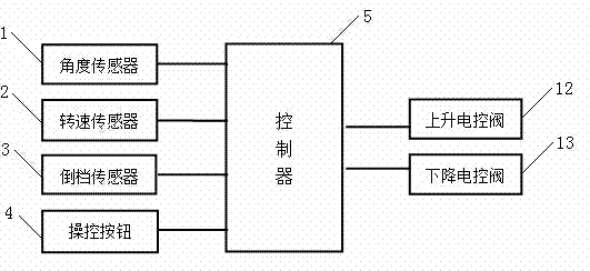
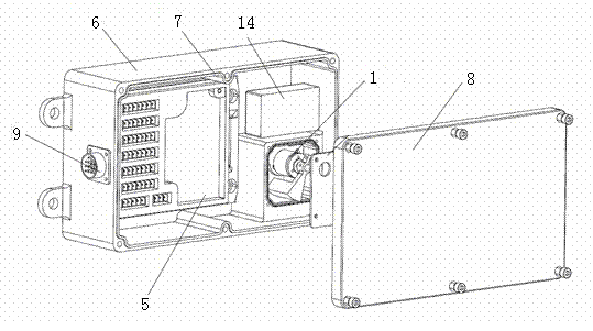
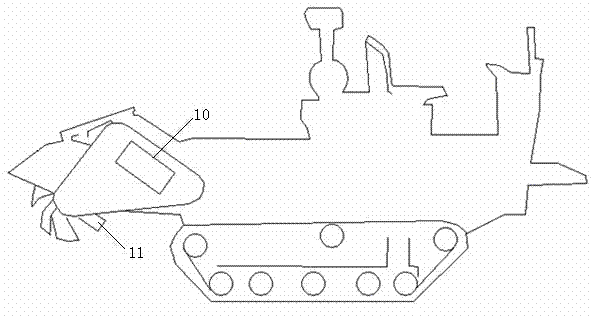
[0027] refer to Figure 1-Figure 3 , the working height adjustment control system of the rotary tiller cutter of the present embodiment includes a control box 10, an angle sensor 1, a rotational speed sensor 2, a reverse gear sensor 3 and a control button 4; the control box 10 includes a casing 6, a waterproof ring 7. Housing cover 8, controller 5 and signal cable connector 9, the controller 5 is installed in the housing 6, the signal cable connector 9 is installed on the housing 6, the signal cable connector 9 is connected to the controller 5, the housing cover 8 is connected to the housing 6 through the waterproof ring 7; the angle sensor 1 is installed in the control box 10, and the control box 10 is installed on the side of the rotary tiller cutter 11, and the angle sensor 1 Connect to the controller 5 through the signal cable connector 9; the rota...


PUM


Abstract

The invention relates to a working height adjusting and control system and method for a rotary tillage tool of a rotary cultivator. The system comprises a control box, an angle sensor, a rotating speed sensor, a reverse gear sensor and a control button. The control box comprises a shell, a waterproof ring, a shell cover, a controller and a signal cable connector. The angle sensor is installed on the side face of the rotary tillage tool of the rotary cultivator, and the angle sensor is connected with the controller through the signal cable connector. The rotating speed sensor is installed beside a fly wheel of an engine of the rotary cultivator and connected with the controller through the signal cable connector. The reverse gear sensor is installed beside an advancing and reverse gear switching mechanism of the rotary cultivator. The control button is connected with controller through the signal cable connector. The controller is connected with an ascending electronic control valve and a descending electronic control valve which are arranged on the rotary tillage tool of the rotary cultivator. The invention further includes the working height adjusting and control method for the rotary tillage tool of the rotary cultivator. By means of the working height adjusting and control system and method, the working height of the rotary tillage tool of the rotary cultivator can be effectively adjusted under different working conditions, operation is easy and convenient, and the use effect is good.

Description

technical field [0001] The invention relates to a control system and method for adjusting the working height of a rotary tiller cutter of a rotary tiller. Background technique [0002] At present, when the agricultural rotary tillers used in the market are plowing the land, if the cultivated land is uneven, the handle is usually manually controlled by manual observation to adjust the height and depth of the rotary tiller. The operation is cumbersome and the error is large. Sometimes due to mistakes in observation and judgment or the plowing ground is hard, the rotary tillage tool is not lifted in time, the depth of the rotary tillage is too deep, and the engine is overloaded, resulting in shutdown, tool deformation, and loss of the conveyor belt. In severe cases, the speed change may occur. The box is damaged and scrapped. [0003] In addition, due to the different areas and shapes of the cultivated land, in order to reduce missing tillage, it is necessary to reverse the ve...

Claims


Application Information

Patent Timeline
Patent Type & Authority Applications(China)
IPC IPC(8): A01B33/08
Inventor 李惠远
Owner 李惠远
Why Eureka
Try Eureka