Ground brake resistor of urban rail transit

A technology of urban rail transit and braking resistors, applied in electric braking systems, electric vehicles, transportation and packaging, etc., can solve the problems of land acquisition and coordination of auxiliary buildings on the ground, large heat generation and large volume of ground braking resistors, etc.

Inactive Publication Date: 2015-07-08
CHINA RAILWAY SIYUAN SURVEY & DESIGN GRP
View PDF6 Cites 2 Cited by
  • Summary
  • Abstract
  • Description
  • Claims
  • Application Information

AI Technical Summary

Problems solved by technology

[0016] The purpose of the embodiments of the present invention is to provide a ground braking resistor for urban rail transit, so as to solve the problem of heat dissipation caused by the high heat generation and large volume of the ground braking resistor in the prior art, the shortage of civil construction area in the subway station, and the land acquisition of auxiliary buildings on the ground. problems with coordination

Method used


Image

  • Ground brake resistor of urban rail transit
  • Ground brake resistor of urban rail transit
  • Ground brake resistor of urban rail transit

Examples


Embodiment 1

[0048] Embodiment 1 provided by the present invention is an installation embodiment of an urban rail transit ground braking resistor provided by the present invention. In this embodiment, the wall-mounted resistance box is placed in the box protection transition piece, and the box body protection transition piece is placed On the mounting base, the mounting base is bolted to the wall.

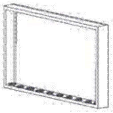
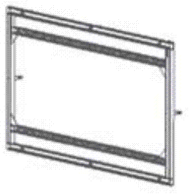
[0049] Such as figure 1 Shown is a schematic structural view of the box protection transition piece of the urban rail transit ground braking resistor provided by the embodiment of the present invention. figure 1 It can be seen that the embodiment of the box protection transition piece is a rectangular parallelepiped frame, and the rectangular parallelepiped frame includes four sides up, down, left, and right, the size of which is compatible with the size of the wall-mounted resistance box, and the bottom surface of the box body protection transition piece is also provided with a bottom cooling ...

Embodiment 2

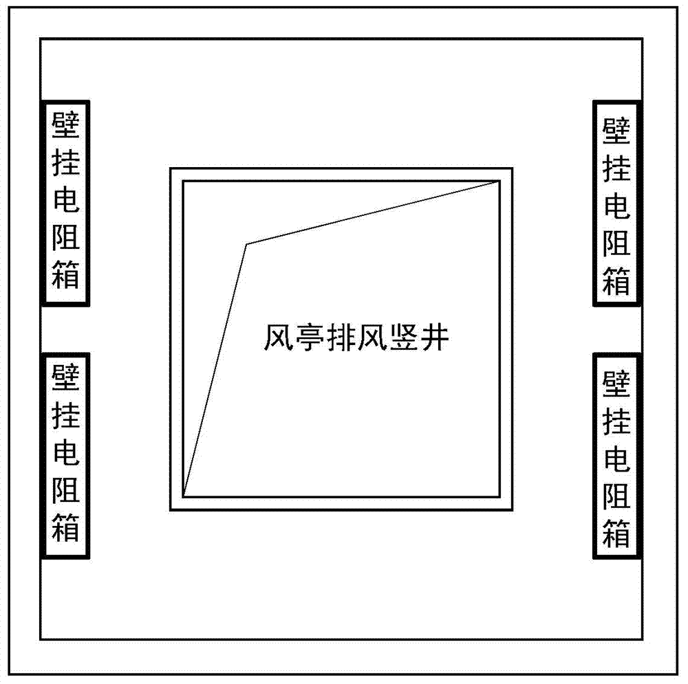
[0051] Embodiment 2 provided by the present invention is a placement embodiment of an urban rail transit ground braking resistor provided by the present invention. In this embodiment, the exhaust shaft of the wind pavilion is expanded for a certain distance in a direction parallel to the wellhead of the exhaust shaft. , that is to increase the cross-sectional size of the exhaust shaft, and place the wall-mounted resistance box on the surrounding walls after the exhaust shaft of the wind pavilion is expanded.

[0052] Such as image 3 Shown is a schematic diagram of an urban rail transit ground braking resistor placed in an exhaust booth provided by an embodiment of the present invention, as shown in Figure 4 Shown are respectively a schematic diagram of an urban rail transit ground braking resistor placed in a low-wind pavilion provided by an embodiment of the present invention, image 3 is the section along the direction parallel to the wellhead of the exhaust shaft, imag...


PUM


Abstract

The invention is suitable for the technical field of substation design in urban rail transit and provides a ground brake resistor of urban rail transit. Control equipment and chopping equipment of the ground brake resistor are arranged in an underground substation. A resistor part of the ground brake resistor includes one or more wall hanging resistance boxes arranged on a wall at ventilation positions of an urban rail transit system. The wall hanging resistance boxes comprise groups of resistance grid units and box protecting shells. The box protecting shells are each in the shape of a cuboid and heat dissipation windows are arranged in six faces of each box protecting shell. The group number of resistance grid units is determined according to the actual mounting environment, and the sizes of the box protecting shells can be adjusted according to the group number of the resistance grid units. The resistor equipment of the ground brake resistor is arranged in form of one or more wall hanging resistance boxes, so that the problems of heat dissipation, land occupancy and coordination and the like due to large heat dissipation amount and large size of the ground brake resistor are solved.

Description

technical field [0001] The invention belongs to the technical field of urban rail transit substation design, in particular to a ground braking resistor for urban rail transit. Background technique [0002] At present, the ground regenerative energy absorption device schemes adopted at home and abroad with relatively mature technology mainly include resistance energy consumption type, capacitor energy storage type, flywheel energy storage type, inverter feedback type, inverter + resistance hybrid type and two-way controllable type, etc. . [0003] Capacitive energy storage type, flywheel energy storage type, two-way controllable type and other equipment are not domestically produced at present, or there are export restrictions, or the price is too high, and the feasibility of domestic promotion and application is small. [0004] Resistive braking is simple, reliable, low in cost, and easy to be accepted by users. Regardless of whether resistance braking is set alone or mixed...

Claims


Application Information

Patent Timeline
Patent Type & Authority Applications(China)
IPC IPC(8): B60L7/02
Inventor 叶飞王开康温建民方刚
Owner CHINA RAILWAY SIYUAN SURVEY & DESIGN GRP
Why Eureka
Try Eureka