
Adjustable front canopy clamping cable

A cable and clip technology is applied in the field of adjustable front probe beam and cable, which can solve the problem of affecting the normal use of the front probe beam, the longitudinal failure of the anchor rod and the inability to form a straight line, and the front probe beam passing through less than three clip cables. There are three cables inside or barely penetrated, and only the lower bottoms of two cables are dragging the front probe beam; it may only be able to pass through two cables, etc.

Inactive Publication Date: 2015-07-08
刘允勇
View PDF5 Cites 0 Cited by
  • Summary
  • Abstract
  • Description
  • Claims
  • Application Information

AI Technical Summary

Problems solved by technology

The traditional front beam clamping cable is directly fixed on the exposed part of the anchor rod. The position of the clamping cable changes according to the position of the anchor rod. The roadway turning curve, turning point or deviation during construction will cause the bolt to be out of line in the longitudinal direction; When the roof fluctuates, the height of the cables changes accordingly. The three cables cannot form a straight line. The front beam cannot penetrate or barely penetrates the three cables. The bottom drags the front beam; it may only pass through the two clamping cables, which affects the normal use of the front beam and poses a great threat to safe production; the traditional front beam clamping cable is welded with an anchor bolt When using the cap, screw the front probe beam clamp cable on the exposed thread of the roof anchor rod
The exposed threads of the roof bolts are of different lengths, and the short ones are only 1~3 threads. It is closed, and the cable can only be disassembled when the front beam is separated from the card cable, and only after the card cable is installed can the front beam be strung over, which brings great benefits to the forward movement and regular use of the front beam. inconvenient

Method used


Image

  • Adjustable front canopy clamping cable
  • Adjustable front canopy clamping cable
  • Adjustable front canopy clamping cable

Examples


Embodiment Construction

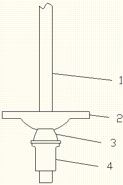
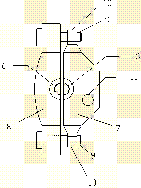
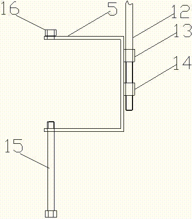
[0021] An adjustable probe beam card cable, such as figure 1 , 2 , 3, 4, 5, 6, 7, 8, and 9, including the anchor rod 1, the anchor plate 2 installed on the anchor rod, the anchor nut 4 supporting the anchor plate, and the cable frame supporting the front beam 5. A tapered self-aligning washer 3 with a small upper end and a large lower end is arranged between the anchor plate and the anchor rod nut. A clip is installed on the self-aligning washer, and the clip includes a clip front plate 7 and a The clip rear plate 8, the corresponding positions of the clip front plate and the clip rear plate are respectively provided with half symmetrical self-aligning washer sockets 6, and the size of the self-aligning washer socket matches the size of the self-aligning washer, and the The self-aligning washer is just clamped in the self-aligning washer nest. Both ends of the clip front plate and the clip rear plate are connected by bolts, clamping bolts 9 are installed at both ends of the ...


PUM


Abstract

The invention relates to an adjustable front canopy clamping cable. The clamping cable comprises an anchor rod, an anchor disc, an anchor rod nut and clamping cable frames, a tapered aligning gasket with the upper end smaller and the lower end bigger is arranged between the anchor disc and the anchor rod nut, a clamp is installed on the aligning gasket, the clamp comprises a front clamp plate and a rear clamp plate, the front clamp plate and the rear clamp plate are each provided with a half aligning gasket groove at the corresponding position, the half aligning gasket grooves are symmetrical, and the aligning gasket grooves and the aligning gasket are matched in dimension; a connecting bolt hole is formed in the front clamp plate, and a connecting bolt is arranged in the connecting bolt hole; the lower end of the connecting bolt is provided with a connecting nut which is matched with the connecting bolt, the connecting nut is welded to one side of each clamping cable frame, a guide sleeve is welded to the side frame, where the connecting nut is welded, of the clamping cable frame, the guide sleeve is arranged at the upper end of the connecting nut, and the connecting bolt is inserted into the guide sleeve. According to the adjustable front canopy clamping cable, by adjusting the height and the position in the horizontal direction of the clamping cable frames, it is guaranteed that the three clamping cable frames are located on the same line, and therefore a front canopy is convenient to install and detach.

Description

technical field [0001] The invention relates to a temporary support system for ensuring the safety of construction personnel during roadway excavation, in particular to an adjustable front probe beam clamping cable. Background technique [0002] The safety regulations stipulate that there are no less than three clamping cables for each probe beam. The traditional front beam clamping cable is directly fixed on the exposed part of the anchor rod. The position of the clamping cable changes according to the position of the anchor rod. The roadway turning curve, turning point or deviation during construction will cause the bolt to be out of line in the longitudinal direction; When the roof fluctuates, the height of the cables also changes. The three cables cannot form a straight line. The bottom drags the front beam; it may only pass through the two clamping cables, which affects the normal use of the front beam and poses a great threat to safe production; the traditional fr...

Claims


Application Information

Patent Timeline
Patent Type & Authority Applications(China)
IPC IPC(8): E21D17/10
CPCE21D17/10
Inventor 刘允勇刘洁李亚飞徐洪涛张新永曹现帮李世玺徐涛吕润生雷伟伟
Owner 刘允勇
Learn More