
Rolling object monocular pose measurement method based on color image

A color image, pose measurement technology, used in measurement devices, photogrammetry/video measurement, surveying and navigation, etc., can solve the problems of occlusion of image features, difficulty in covering the target movement space, and small measurement field of view.

Active Publication Date: 2015-07-08
DALIAN UNIV OF TECH
View PDF3 Cites 28 Cited by
  • Summary
  • Abstract
  • Description
  • Claims
  • Application Information

AI Technical Summary

Problems solved by technology

[0004] The technical problem to be solved in the present invention is to overcome the problems of the prior art, and to invent a method for measuring the monocular pose of rolling objects based on color images. The camera collects the image of the target object, which overcomes the problem that the traditional binocular vision system has a small measurement field of view and is difficult to cover the entire movement space of the target; compared with the binocular system that uses two cameras for measurement, the monocular measurement system has simple equipment; in addition, There is no need to consider the problem of simultaneous triggering of two cameras; the self-illuminated marker points evenly distributed along the circumference of the gyratory can solve the problem of image features being blocked when the object rolls, and the marker points are coded in a wrap-around color coding method without feature Matching can realize the pose measurement of the moving target and meet the requirements of monocular measurement

Method used


Image

  • Rolling object monocular pose measurement method based on color image
  • Rolling object monocular pose measurement method based on color image
  • Rolling object monocular pose measurement method based on color image

Examples


Embodiment Construction

[0032] The specific embodiments of the present invention will be described in detail below in conjunction with the technical solutions and accompanying drawings.

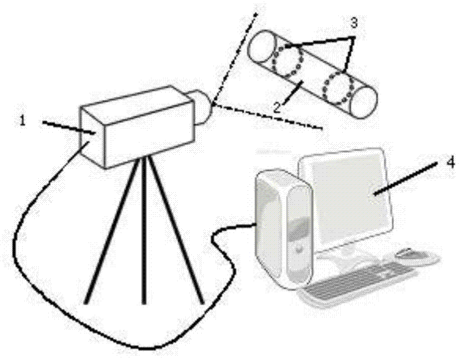
[0033] attachedfigure 1 This is the schematic diagram of the monocular pose measurement method for rolling objects based on color images. This method arranges color-coded marking points on the surface of the object, and uses camera 1 to collect images during the movement of rotating body 2. After camera calibration, marker feature extraction and position Pose acquisition solution calculates the pose information of the target. First, arrange the color self-illumination units on the surface of the rotator 2 under test according to the pre-designed coding method, and adjust the focal length and angle of the monocular camera 1 so that the measurement field of view completely covers the activity space of the moving target 2 . The graphics workstation 4 is used to calibrate the camera, and the computer is used to extract ...


PUM


Abstract

The invention provides a rolling object monocular pose measurement method based on a color image, belongs to the field of computer vision and relates to a method of rolling object model pose measurement with the principle of monocular vision with combination of a self-luminous coding mark point. In the method, by means of a manner of surrounding grouped arrangement, color-coded self-luminous mark points are arranged on a surface of a to-be-measured object, and then post measurements, comprising six parameters: displacements in the directions of X, Y and Z, pitching angle, yaw angle and rolling angle. With the color-coded self-luminous mark points on the surface of the to-be-measured object as a characteristic marker, a color-coded characteristic image on the surface of the moving target is collected. Finally, on the basis of calibration by a high-speed camera, through an image processing step including recognition and extraction of the image being marked by the color-coded mark, the target position pose information of the rolling object is solved. In the method, by means of a monocular camera with combination of color image for measurement, the method is high in measurement efficiency, is simple in required equipment and is wide in available range.

Description

technical field [0001] The invention belongs to the technical field of computer vision measurement and relates to a method for measuring the spatial position and attitude of a revolving body with rolling motion. Background technique [0002] With the gradual improvement and improvement of aerospace and aviation technology, the measurement of the position and orientation information of the aircraft and its objects during the execution of the mission plays an extremely important role in the design and test phase of the aircraft. Machine vision measurement technology has the advantages of non-contact, flexibility, and high measurement accuracy, and is widely used in the pose measurement of aircraft and its launch model. The characteristics of fast moving speed and large motion space of rolling objects in the actual motion process put forward higher requirements for the pose measurement of moving objects. [0003] Liu Wei of Dalian University of Technology and others proposed a...

Claims


Application Information

Patent Timeline
IPC IPC(8): G01C11/00
CPCG01C11/00G01C11/36
Inventor 刘巍陈玲贾振元李肖马鑫尚志亮
Owner DALIAN UNIV OF TECH
Learn More