Environment defocusing self-adaptation compensation method for airborne laser communication system

An adaptive compensation and communication system technology, applied in optics, optical components, free space transmission, etc., can solve problems such as slow response speed, large actuator size, difficult to control precision, etc., achieve less error accumulation, fast response speed, The effect of low power consumption

Inactive Publication Date: 2015-07-08
CHANGCHUN UNIV OF SCI & TECH
View PDF4 Cites 15 Cited by
  • Summary
  • Abstract
  • Description
  • Claims
  • Application Information

AI Technical Summary

Problems solved by technology

However, this method only compensates for a certain level of defocus, and cannot comprehensively perform real-time dynamic compensation for defocus caused by other environments such as air pressure and aero-optical effects.
The application number is 201210445099.7, and the patent titled "the device for compensating the optical focal plane based on the wedge prism" uses the movement of the prism and the lens group as the actuator to compensate the defocus, but the actuator of this method is large in size and complex in structure. and slow response
At present, there is still a common method, which is to control the relative position between the moving detector and the optical system for defocus compensation, but this method has a complex structure and is difficult to control the accuracy

Method used


Image

  • Environment defocusing self-adaptation compensation method for airborne laser communication system
  • Environment defocusing self-adaptation compensation method for airborne laser communication system

Examples


Embodiment Construction

[0018] The present invention will be further described below in conjunction with drawings and embodiments.

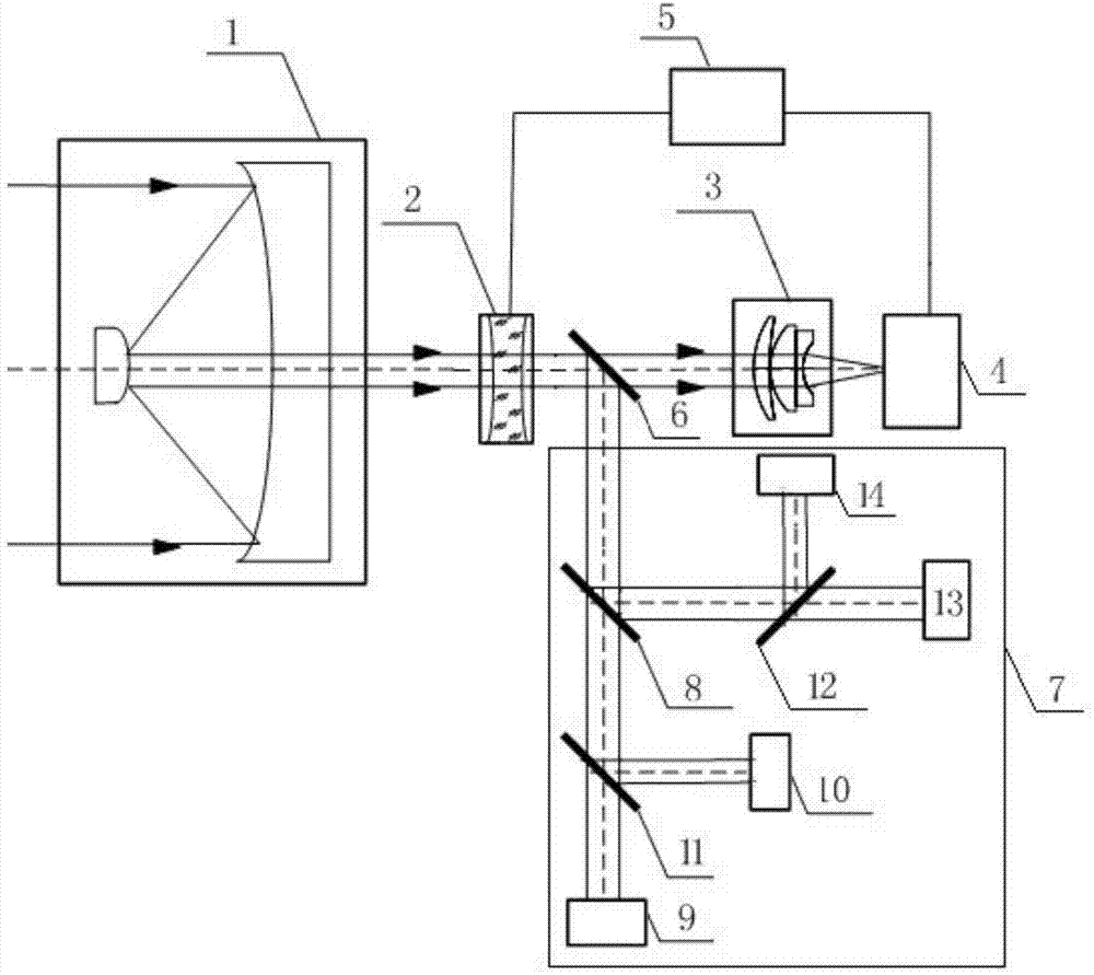
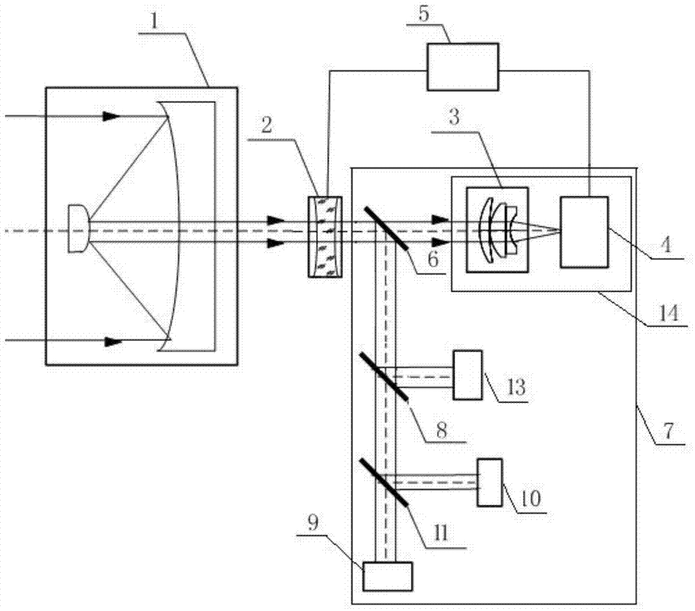
[0019] Depend on Figure 1-Figure 2 It can be seen that an airborne laser communication system environmental defocus adaptive compensation method of the present invention includes the following steps,

[0020] Step 1: Use the optical antenna 1 to shrink the laser beam of the airborne laser communication system, and the reduced laser beam enters the liquid lens 2 arranged along the optical axis at the rear of the optical antenna 1, and the liquid lens 2 is controlled by an electronic control signal , changing the focal length continuously;

[0021] Step 2: After the laser beam passes through the liquid lens 2, it is split by the first beam splitter 6, and one path of the laser beam is converged on the image detector 4 by the defocus detection optical module 3, and one path of the laser beam enters the second optical system in the transceiver sub-optical system 7. The b...


PUM


Abstract

The invention relates to an environment defocusing self-adaptation compensation method for an airborne laser communication system, and belongs to the field of space laser communication. An optical antenna is used for shrinking a laser bundle of the airborne laser communication system; after passing through a liquid lens, the laser bundle is focused on an image detector through a defocusing detection optical module, and the image detector interprets the diameter of laser spots and transmits the diameter information of the laser spots to a system controller; the system controller obtains the environment defocusing amount of the laser communication optical system through calculation, then obtains the needed compensation amount of the liquid lens, converts the compensation amount of the liquid lens into an electric control signal and transmits the electric control signal to the liquid lens, and the liquid lens receives the electric control signal, changes the curvature radius and then changes the focal length to perform defocusing self-adaptation compensation. Compared with the prior art, the system controller is used for controlling the liquid lens to perform dynamic environment defocusing compensation without moving any optical components, response speed is high, and the structure is easy to lighten and miniaturize.

Description

technical field [0001] The invention belongs to the field of space laser communication, in particular to an adaptive compensation method for environment defocus of an airborne laser communication system. Background technique [0002] For the laser communication terminal on the airborne platform, the expansion and contraction of materials caused by temperature, the change of air density caused by air pressure, and the aero-optical effect caused by high-speed flight will all cause the optical system in the communication terminal to defocus. It is mentioned in the literature "Aerodynamic Optics Effect and Compensation in Airborne Laser Communication" and "The aero optics effect on near space laser communication optical system" that the defocus caused by temperature or boundary layer can be adjusted by using fixed optical mirror group compensate. However, this method only compensates for a certain level of defocus, and cannot comprehensively perform real-time dynamic compensati...

Claims


Application Information

Patent Timeline
Patent Type & Authority Applications(China)
IPC IPC(8): G02B7/28G02B3/14H04B10/11
CPCG02B3/14G02B7/28H04B10/11
Inventor 胡源姜会林佟首峰张立中
Owner CHANGCHUN UNIV OF SCI & TECH
Why Eureka
Try Eureka