Liquid flow monitoring device

A monitoring device and liquid flow technology, applied in the field of sensor detection, can solve problems such as easy to be corroded, difficult to detect small flow rate, etc., and achieve the effect of accurate measurement results and high control precision

Inactive Publication Date: 2015-07-08
柳州市金旭节能科技有限公司
View PDF4 Cites 1 Cited by
  • Summary
  • Abstract
  • Description
  • Claims
  • Application Information

AI Technical Summary

Problems solved by technology

However, the flow switch has the defect that it is difficult to ...

Method used


Image

  • Liquid flow monitoring device
  • Liquid flow monitoring device

Examples


Embodiment

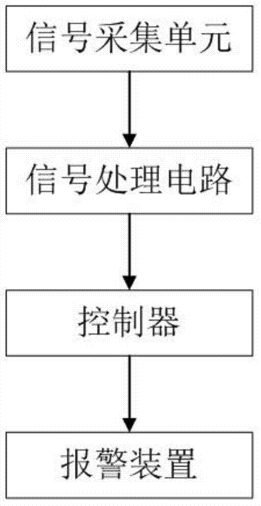
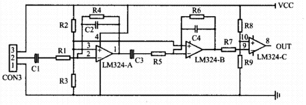
[0019] Example: figure 1 The control block diagram of the liquid flow monitoring device provided by the embodiment of the present invention, it can be clearly seen from the figure that the liquid flow monitoring device provided by this embodiment includes a signal acquisition unit, a signal processing circuit, a controller and an alarm device, wherein, The signal acquisition unit includes a turbine fixed in the water pipe and a magnetoresistive sensor, the surface of the turbine is perpendicular to the direction of liquid flow in the water pipe, and the magnetoresistive sensor for detecting the turbine speed is close to the turbine, figure 2 The schematic diagram of the signal processing of the liquid flow monitoring device provided by the embodiment of the present invention, the signal processing circuit is a three-terminal differential circuit, the signal processing circuit includes three operational amplifiers, the output terminal of the signal acquisition unit is connected...


PUM


Abstract

The invention relates to the field of sensor detection and discloses a liquid flow monitoring device. The liquid flow monitoring device comprises a signal collection unit, a signal processing circuit, a controller and a warning device. The signal collection unit comprises a turbine and a magnetic resistance sensor which are fixedly arranged in a water pipe. The surface of the turbine is perpendicular to the flowing direction of liquid in the water pipe, and the magnetic resistance sensor used for detecting the rotating speed of the turbine is close to the turbine. The signal processing circuit is a three-terminal differential circuit and comprises three operational amplifiers. The output end of the signal collection unit is connected with the input end of the signal processing circuit. The signal processing circuit outputs a processed signal to the controller. The controller controls the warning device according to the received signal. The liquid flow monitoring device is high in corrosion resistance, accurate in measurement result and high in control accuracy.

Description

technical field [0001] The invention relates to the field of sensor detection, in particular to a liquid flow monitoring device. Background technique [0002] The normal operation of industrial equipment or instruments can be reflected by the flow rate of the liquid in the delivery pipeline. If the flow rate of the liquid in the delivery pipeline is too high, the thermal cycle of the system will accelerate and the power loss of the equipment or instrument will be too large, resulting in power resources. waste; if the liquid flow rate in the pipeline is too low, the thermal cycle of the system will cause the equipment or instrument to "dry burn". Therefore, the liquid flow rate in the pipeline is always within a reasonable monitoring range. It has a great influence on the work efficiency and lifespan. [0003] In the prior art, the flow switch is used to detect the flow rate of the liquid in the pipeline, and then monitor whether the equipment is working normally. The most w...

Claims


Application Information

Patent Timeline
IPC IPC(8): G05D7/06
Inventor 熊庆华史永凯
Owner 柳州市金旭节能科技有限公司
Why Eureka
Try Eureka