Spark plug

A spark plug and main body technology, applied in the field of spark plugs, can solve the problems of increasing the output rate of spark plug waste parts, the influence of engine work, and the increase in processing difficulty, so as to achieve convenient measurement and adjustment of ignition gap, high applicability, stability and accuracy high degree of effect

Active Publication Date: 2015-07-08
张蝶儿
View PDF7 Cites 12 Cited by
  • Summary
  • Abstract
  • Description
  • Claims
  • Application Information

AI Technical Summary

Problems solved by technology

[0004] However, this traditional spark plug has the following disadvantages when in use: First, after the center electrode and the ground electrode generate sparks, because the ground electrode is located between the center electrode and the combustion chamber, the spark is blocked from being released directly to the combustion chamber, so the spark can only go to the combustion chamber. The side release increases the ignition time, and the ignition is not sufficient, which reduces the ignition efficiency; second, because the ground electrode and the center electrode are directly in the combustion chamber, and the ignition is carried out in a relatively open space, the spark dispersion is not violent enough at the moment of ignition, so Slower rate of spark release
[0007] First, although the exhaust hole allows the spark to be released directly towards the combustion chamber, the ignition time will be delayed due to the long release path
[0008] Second, the size, calorific value and other parameters of traditional spark plugs are all customized according to the requirements of engine development, and there are already fixed requirements. If the design of spark plugs is changed after the vehicle is launched, such as changing the length and thickness of the spark plug shell or the insulator The length of the spark plug and so on will affect the working state of the spark plug, and then have a certain impact on the engine work. This invention has greatly changed the structure and size of the spark plug housing, so it will have a negative impact on the applicability and stability of the original engine.
[0009] Third, since the center electrode and the ground electrode are placed in a relatively closed spark plug shell, it is difficult for the mixed gas in the combustion chamber to enter, and the fluidity of the mixed gas is poor, which may easily lead to insufficient ignition
Since the positions of the spark plug housing and the fuel injector in the combustion chamber are relatively fixed, when the ignition gap is located in the housing, the distance between the ignition point and the fuel injector will be too far, the oil mist will be thin, and the ignition effect will not be ideal
[0010] Fourth, placing the center electrode and the ground electrode in the spark plug shell will greatly increase the difficulty of processing due to the need for processing in the internal structure of the shell, especially the direct measurement and adjustment of the distance between the ground electrode and the center electrode becomes Impossible, the usual tools can’t be realized, only the method of estimating according to the design drawings can be adopted, but this will cause a large error, and because the spark plug has very precise requirements for the ignition gap, the general gap is 0.3-1.5 Between mm, if this requirement is not met, it will lead to failure to flashover, which greatly increases the waste output rate of spark plugs

Method used


Image

  • Spark plug
  • Spark plug
  • Spark plug

Examples


Embodiment 1

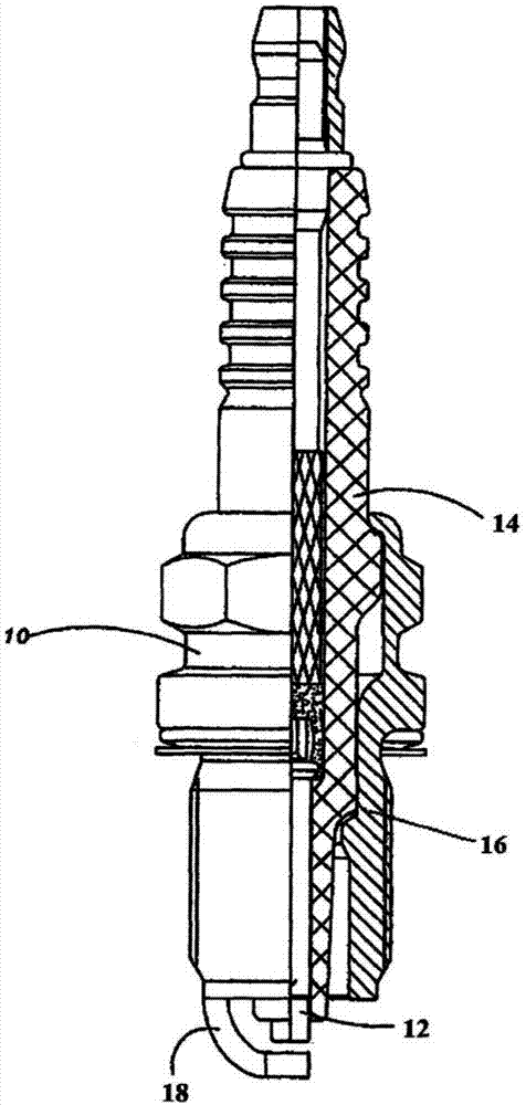
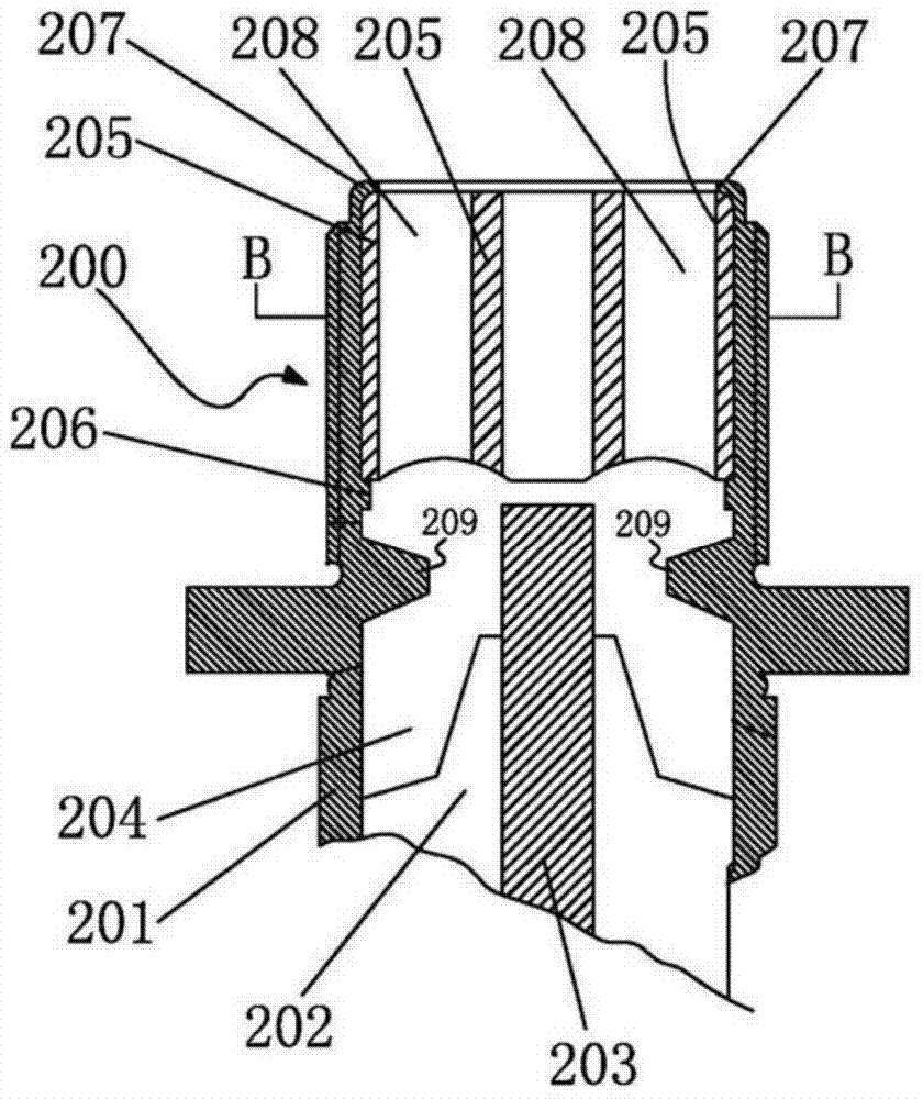
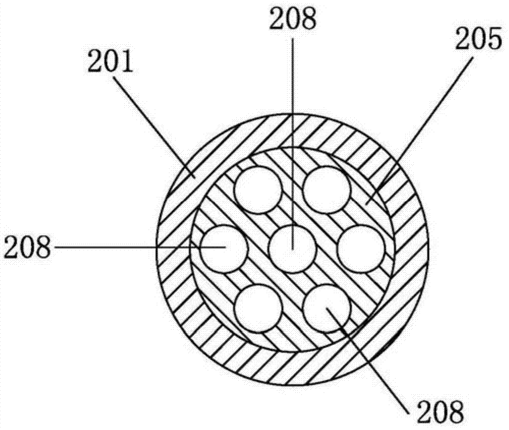
[0048] Please also see Figure 4 and Figure 5 ,in, Figure 4 A schematic diagram of the structure of the spark plug, Figure 4 A partial cross-sectional schematic diagram of the ignition unit 5 is Figure 5 The cross-sectional view of the A-A direction in the middle.

[0049] The spark plug provided by the present invention includes a center electrode 1 , an insulator 2 , a shell 3 , a connecting rod 4 and an ignition unit 5 . The insulator 1 has a shaft hole extending along the axis direction, and the center electrode 1 is inserted into the shaft hole with the end exposed. The casing 3 is a hollow column, sheathed on the surface of the insulator 2, and the end of the center electrode is exposed outside the casing. The ignition unit 5 is located outside the housing 3 and is fixedly connected to the end of the housing 3. It can be connected to the housing 3 through at least one connecting rod 4. In particular, in this embodiment, the ignition unit 5 is connected through two...

Embodiment 2

[0057] Embodiment two of the present invention, refer to Figure 9 and 10 . Figure 9 is a structural schematic diagram of the spark plug, wherein, a partial cross-sectional schematic diagram of the ignition unit 5 is Figure 5 The cross-sectional view of the A-A direction in the middle. Figure 10 is a three-dimensional structure diagram of the ground electrode. Embodiment 2 of the present invention is basically the same as Embodiment 1, except that the center electrode 1 is not inserted into the through hole of the annular sheet 511b, but outside the through hole; meanwhile, the diameter of the through hole is larger than that of the center. The diameter of the electrode is small, therefore, the axial space between the annular sheet 511b and the central electrode 1 acts as an ignition gap; in addition, except for the step 532, the inner wall of the main body 53b forms a conical detonation cavity, which is close to the ground The diameter of the end face of electrode 51 i...

Embodiment 3

[0059] Embodiment three of the present invention, see Figure 11 , which is the front view of the ground electrode. The third embodiment is basically the same as the second embodiment, except that the ground electrode 51c is not provided with an annular sheet 511b and a fixed foot 512, but with a plurality of through holes, the diameter of which is larger than that of the through hole on the baffle plate 52. The diameter is small, so the effect similar to that of the second embodiment can also be achieved, that is, guiding the main airflow to inject towards the direction of the combustion chamber.


PUM


Abstract

The invention relates to a spark plug. The spark plug comprises an insulator, a center electrode, a shell and an ignition unit fixed to the exterior of the shell. The ignition unit is provided with a burning and blasting cavity and comprises a body part and a grounding electrode; the body part is a hollow column, and the hollow part is the burning and blasting cavity; the grounding electrode is arranged at the end, close to the center electrode, of the body part and provided with a through hole. The center electrode is opposite to the through hole, and the center electrode and the grounding electrode form an ignition gap. The spark plug is easy to machine and good in applicability and stability, the accuracy of the ignition gap is high, the flowability of mixed gas is high, sparks are released in a small space in a blasting mode, and a continuous jetting effect can be achieved.

Description

technical field [0001] The invention relates to an ignition device, in particular to a spark plug used in an internal combustion engine. Background technique [0002] The spark plug is an ignition device installed on the internal combustion engine to ignite the mixed gas in the combustion chamber. [0003] see figure 1 , which is a schematic structural diagram of a conventional spark plug. The spark plug 10 includes a center electrode 12 , an insulator 14 , a housing 16 and a ground electrode 18 . The insulator 14 is a ceramic insulator with an axis hole extending along the axis, and the center electrode 12 is inserted through the axis hole of the insulator 14 . The casing 16 is sheathed on the outer periphery of the insulator 14 . The ground electrode 18 is connected to the end of the casing 16 , and bends to extend opposite to the center electrode 12 , forming a spark discharge gap with the center electrode 12 . An electric arc is generated between the center electrod...

Claims


Application Information

Patent Timeline
Patent Type & Authority Applications(China)
IPC IPC(8): H01T13/32H01T13/54
Inventor 张蝶儿
Owner 张蝶儿
Why Eureka
Try Eureka