Winding type permanent magnet coupling transmission device

A permanent magnetic coupling and transmission technology, which is applied in the direction of electromechanical transmission, synchronous clutch/brake, asynchronous induction clutch/brake, etc., can solve the problems of increased volume, small output power, complex structure, etc., and achieve simple maintenance, The effect of simple structure and small volume

Active Publication Date: 2015-07-08
JIANGSU MAGNET VALLEY TECH
View PDF13 Cites 32 Cited by
  • Summary
  • Abstract
  • Description
  • Claims
  • Application Information

AI Technical Summary

Problems solved by technology

[0006] Therefore, the technical problem to be solved by the present invention is that in the prior art permanent magnet speed regulating device, when changing the output torque, a mechanical actuator needs to be installed, which not only has a complex structure, but also increases the volume and improves the follow-up maintenance workload; At the same time, there is a loss of slip power. When the input power is constant, the larger the slip power will lead to the smaller the output power, and the slip power is directly dissipated in the form of heat energy. When the speed of the permanent magnet speed control device is greater, it will generate heat. The more severe the problem, the lower the transmission efficiency of the permanent magnet speed regulating device and the greater the energy loss; and then provide a winding type permanent magnet coupling transmission device with simple structure, low energy loss and high transmission efficiency

Method used


Image

  • Winding type permanent magnet coupling transmission device
  • Winding type permanent magnet coupling transmission device
  • Winding type permanent magnet coupling transmission device

Examples


Embodiment 1

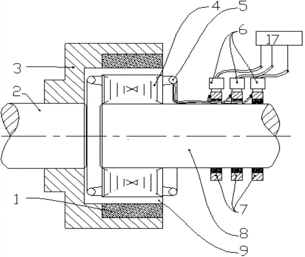
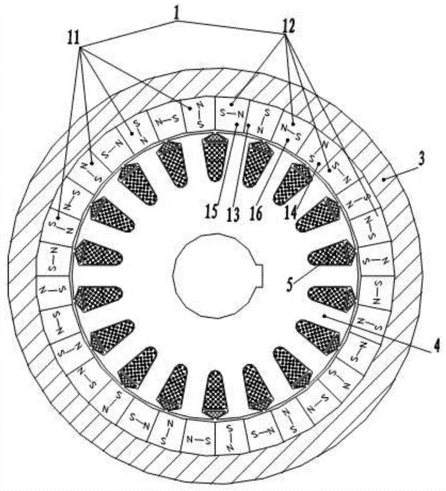
[0050] Such as Figure 1-6 As shown, a winding type permanent magnet coupling transmission device of this embodiment includes a permanent magnet rotor, and a winding rotor coaxial with the permanent magnet rotor and capable of relative rotation between the two; wherein the permanent magnet There is an air gap 9 between the rotor and the winding rotor; the winding rotor is connected with a control structure 17 that can adjust the current of the winding rotor; we know that the torque transmitted by the permanent magnet coupling transmission depends on In addition to the size of the air gap magnetic density (provided by the permanent magnet rotor), it also depends on the size of the conductor rotor current. If the size of the conductor rotor current can be controlled, the output torque can be achieved without a mechanical actuator;

[0051] In this embodiment, the control structure 17 can control the current or voltage of the winding rotor, changing the idea of ​​using a mechanic...

Embodiment 2

[0069] As a convertible implementation mode, the differences between this embodiment and embodiment 1 are:

[0070] On the basis of Embodiment 1, the permanent magnet array in this embodiment also includes a third permanent magnet array 20 embedded between the first permanent magnet array 11 and the second permanent magnet array 12; wherein , the respective magnetic field directions of the first permanent magnet array 11, the second permanent magnet array 12, and the third permanent magnet array 20 respectively form a first angle, a second angle, and a first angle that are not obtuse angles with corresponding radii. Three included angles, the angle difference between the first included angle, the second included angle and the third included angle is 45 degrees respectively.

[0071] Specifically, the third permanent magnet array 20 includes a fifth unit magnet block 21, a sixth unit magnet block 22, a seventh unit magnet block 23, and an eighth unit magnet block 24 arranged at...

Embodiment 3

[0076] As a convertible implementation mode, the differences between this embodiment and embodiment 1 are:

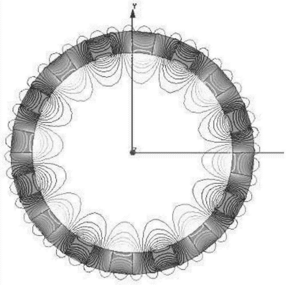
[0077] In this embodiment, the specific structure between the permanent magnet arrays is as Figure 8 As shown; the permanent magnet 1 with the above structure can obtain a single-plane magnetic field, and obtain a nearly sinusoidal air-gap magnetic field.

[0078] Further, in this embodiment, the iron core 4 is a wound iron core, and a plurality of slots for winding the coil are formed on the wound iron core. The number of the grooves is set to be 3n (n=1, 2, 3...). In this embodiment, preferably n is set to 8, that is, the number of the grooves is set to 24, and the specific structure is as follows Figure 9 shown.


PUM


Abstract

The invention relates to a winding type permanent-magnet slip clutch. The winding type permanent-magnet slip clutch comprises a permanent-magnet rotor and a winding rotor coaxial with the permanent-magnet rotor. An air gap is reserved between the permanent-magnet rotor and the winding rotor. A slip ring and a carbon brush are arranged on a second rotating shaft and form a loop together with a coil winding, wherein switch-on or switch-off of the loop can be controlled by an electric switch. An induced current is generated in the coil winding through the slip between the two rotors, the coil winding with the current can be affected by electromagnetic force in the magnetic field of a permanent magnet, and then transmission of torque can be achieved; the electric switch controls switch-on or switch-off of the loop so as to control engagement or disengagement of the permanent-magnet slip clutch. The function of controlling engagement or disengagement of the clutch is achieved through switch-on or switch-off of the electric switch, and besides, the clutch has the overspeed protection function, the overload protection function, the soft start function and the good speed regulation function and can serve as a brake free of frictional contact.

Description

technical field [0001] The invention relates to the field of permanent magnetic coupling transmission, in particular to a winding type permanent magnetic coupling transmission device. Background technique [0002] At present, in terms of speed regulation of large-scale rotating machinery in the prior art, permanent magnet speed control devices (also called permanent magnet couplers or permanent magnet eddy current speed regulators, etc.) have been recognized and praised by users, and their main features are : ①Torque is transmitted through the air gap without mechanical contact. ②It can achieve stepless speed regulation. ③Light-load soft start to reduce the impact of motor starting on the grid. ④Isolate the load vibration and reduce the damage to the equipment caused by the impact load. ⑤ With overload protection function. ⑥ Safe and reliable, reducing equipment repair rate and maintenance costs. ⑦ No electromagnetic wave interference. Among them, the more representati...

Claims


Application Information

Patent Timeline
Patent Type & Authority Applications(China)
IPC IPC(8): H02K51/00
CPCH02K49/06H02K51/00H02K1/223H02K16/005H02K2213/03H02K49/02H02K49/106
Inventor 漆复兴黄海徐俊峰
Owner JIANGSU MAGNET VALLEY TECH
Why Eureka
Try Eureka