
Method for producing a one-piece lock striker

A one-piece, locking technology, applied in the direction of manufacturing tools, applications, building locks, etc., can solve the problems of high mold load, high forming force, etc., and achieve the effect of improving bearing capacity, improving surface characteristics, and good absorption

Inactive Publication Date: 2015-07-08
KIEKERT AG
View PDF6 Cites 2 Cited by
  • Summary
  • Abstract
  • Description
  • Claims
  • Application Information

AI Technical Summary

Problems solved by technology

[0010] In principle, the forming process by means of a plastic change of the predetermined solid starting blank has the problem that high forming forces are required, which at the same time lead to high mold loads

Method used


Image

  • Method for producing a one-piece lock striker
  • Method for producing a one-piece lock striker
  • Method for producing a one-piece lock striker

Examples


Embodiment Construction

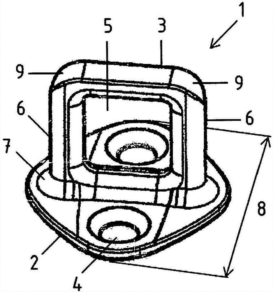
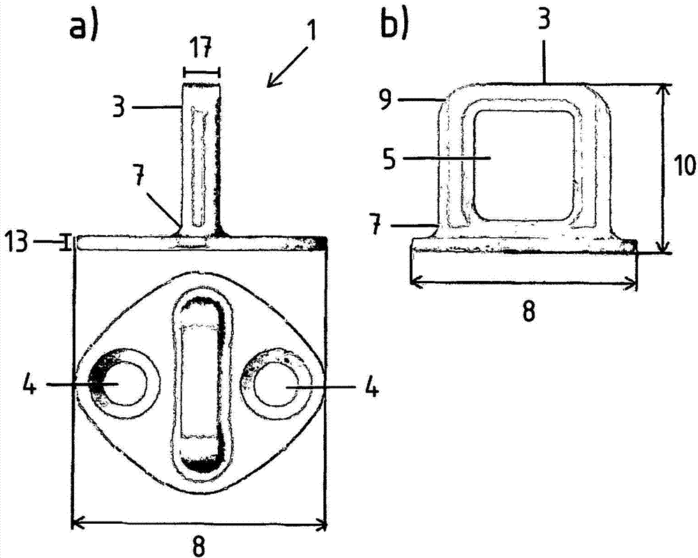
[0037] exist Figure 1 to Figure 2 The buckle 1 shown in is a typical application of the proposed solution. The proposed solution is explained below on the basis of a strike for a motor vehicle lock. However, this should not be construed as limiting the invention thereto.

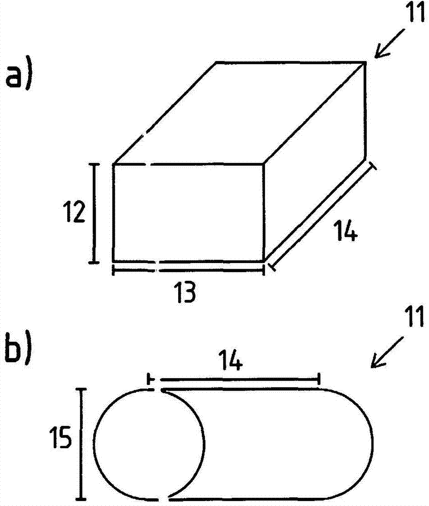
[0038] exist figure 1 The catch shown in has a base plate 2 and a bow 3 . The locking bow 3 has a recess 5 in the center in order to be able to engage with a rotary fork of the lock in the mounted state. The recess 5 can already be formed by a corresponding tool during the shaping of the original blank 11 or can be formed in a subsequent processing step, for example by stamping or cutting. Arranged on both sides of the recess 5 on the locking bow 3 are two legs 6 which are connected to the base plate 2 . The base plate 2 has in this case two openings 4 in the form of holes, which are conically designed and can be fastened, for example, to the body of a vehicle. The region between the base plate 2 and ...


PUM

PropertyMeasurementUnit
areaaaaaaaaaaa
widthaaaaaaaaaa
lengthaaaaaaaaaa

Abstract

The invention relates to a method for producing a one-piece lock striker and to a lock striker produced according to said method. The lock striker (1) comprises a base plate (1) and a lock bracket (3). A metal starter blank (11) is formed into a lock striker by cold forming, in particular by cold upsetting. The starter blank (11) is substantially block-shaped or cylindrical and is formed in such a way that the lock striker (1) becomes strain-hardened.

Description

technical field [0001] The invention relates to a method according to the preamble of claim 1 for producing a one-part lock and a lock produced according to this method. Background technique [0002] The lock catch described is used in particular in locking systems such as motor vehicle locks and motor vehicle locking devices. The invention is explained below with reference to the field of application of motor vehicle locks, but this is not to be understood as limiting the invention thereto. [0003] A latch typically consists of a base plate and a bow (also known as a stop or keyhole). The base plate typically has an opening, for example in the form of a hole, in order thereby, for example, to enable the fastening of the latch to the body of the motor vehicle. The locking bow is shaped in such a way that there is a gap in the middle, so that the locking bow cooperates with the lock or locking device in the mounted state. Thus, the striker can be held in engagement with a...

Claims


Application Information

Patent Timeline
Patent Type & Authority Applications(China)
IPC IPC(8): E05B85/04E05B15/02B21K13/00
CPCB21D53/36B21K13/00E05B85/045B21K1/76Y10T292/68C21D6/002C21D6/004C21D6/005C21D8/005C21D9/0068C22C38/04C22C38/12C22C38/22C22C38/32C22C38/44B21J5/08E05B15/0295
Inventor T·瓦尔德曼F·尼埃杜
Owner KIEKERT AG
Learn More