Automobile suspension mechanism

A technology of automobile suspension and metal rubber, which is applied in the direction of power plant, vehicle parts, jet propulsion device, etc., can solve the problem that the stiffness change curve of rubber parts is difficult to accurately match the actual driving conditions, which affects the quality of the whole vehicle and the service life of parts and components. Vehicle vibration and noise reduction performance and other issues, to achieve the effect of good elastic performance, strong compression and tensile resistance, and good damping performance

Inactive Publication Date: 2015-07-15
NANJING INST OF TECH
View PDF5 Cites 16 Cited by
  • Summary
  • Abstract
  • Description
  • Claims
  • Application Information

AI Technical Summary

Problems solved by technology

[0003] However, the automobile suspension mechanism in the prior art generally uses a single rubber part as an independent shock-absorbing mechanical component. Because the rubber parts are prone to aging and poor corrosion resistance in high and low temperature environments, and the parts are easy to wear, after the car has been driving for a long time, Large changes in mechanical properties will directly affect the performance of vehicle vibration and noise reduction, thereby affecting the quality of the vehicle and the service life of parts
In addition, there are also problems such as the difficulty in accurately matching the stiffness change curve of the rubber parts with the actual driving conditions.

Method used


Image

  • Automobile suspension mechanism
  • Automobile suspension mechanism
  • Automobile suspension mechanism

Examples


Embodiment Construction

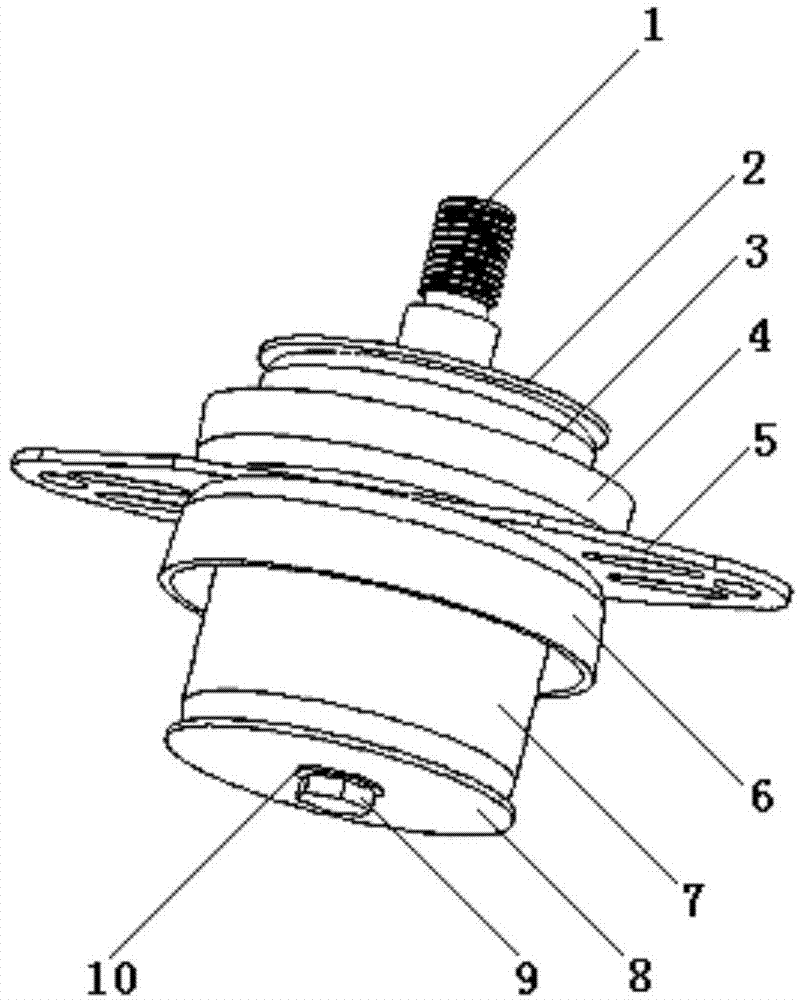
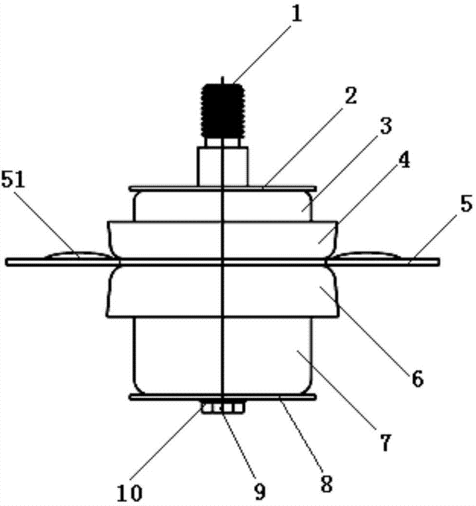
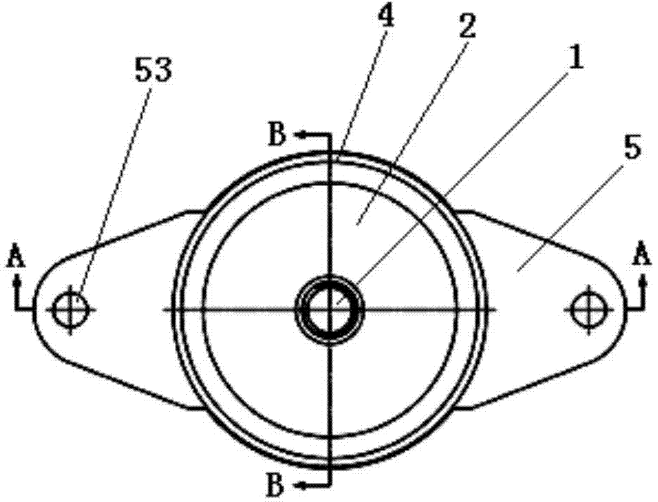
[0033] Below in conjunction with accompanying drawing of description, the present invention will be further described.

[0034] like Figure 1 to Figure 12 As shown, an automobile suspension mechanism includes a connecting screw 1, which is sequentially set on the upper cover plate 2 of the connecting screw 1, the upper metal rubber spring 3, the upper mounting seat 4, the middle mounting plate 5, the lower mounting seat 6, the lower metal Rubber spring 7 and lower cover plate 8; The rod body of described connecting screw rod 1 is provided with mounting portion 11, shoulder 12 and suit portion 13 successively, and described lower cover plate 8 is connected with the end of set portion 13 by fastener; The end of the sleeve portion 13 is provided with an internal thread 130 , the fastener is a mounting bolt 9 , and the lower cover plate 8 is fastened to the end of the sleeve portion 13 by screwing the mounting bolt 9 into the internal thread 130 .

[0035] There is also a conica...


PUM


Abstract

The invention discloses an automobile suspension mechanism. The automobile suspension mechanism comprises a connecting screw rod, an upper cover plate, an upper metal rubber spring, an upper mounting seat, a middle mounting plate, a lower mounting seat, a lower metal rubber spring and a lower cover plate, wherein the upper cover plate, the upper metal rubber spring, the upper mounting seat, the middle mounting plate, the lower mounting seat, the lower metal rubber spring and the lower cover plate sequentially sleeve the connecting screw rod; a rod body of the connecting screw rod is sequentially provided with a mounting part, a convex shoulder and a sleeve part, and the lower cover plate is connected with the tail end of the sleeve part through a fastening piece; the upper and lower mounting seats are respectively connected with the two faces of the middle mounting plate, the upper cover plate and the upper metal rubber spring are sequentially snapped between the convex shoulder and the upper mounting seat, and the lower metal rubber spring is snapped between the lower cover plate and the lower mounting seat; the height of the upper metal rubber spring is 1/2-1/3 that of the lower metal rubber spring. The automobile suspension mechanism has good elastic and damping properties and has the characteristics of high-/low-temperature resistance, corrosion resistance, aging difficulty, no radiation environment fear and the like; due to the adoption of graded earthquake resistance, vibration absorption, vibration isolation and noise reduction can be better realized, and provided compressive and tensile capability can be accurately matched with actual driving conditions.

Description

technical field [0001] The invention relates to a suspension installation part, in particular to an automobile suspension mechanism, which belongs to the technical field of automobile suspension. Background technique [0002] The main function of the automotive powertrain mount is to support and connect the powertrain, withstand dynamic and static loads under various working conditions, and control the displacement of the powertrain in any direction, so that it is compatible with other parts in the cabin and the body. No interference occurs; in addition, vibration absorption, vibration isolation, and noise reduction must be achieved to meet the requirements of vehicle noise, vibration, and comfort. Therefore, the car mount is one of the important assemblies on the car. Its main task is to install the car powertrain, attenuate the vibration transmitted from the powertrain to the support system, and reduce the vibration and noise of the car. [0003] However, the automobile s...

Claims


Application Information

Patent Timeline
Patent Type & Authority Applications(China)
IPC IPC(8): B60K5/12
Inventor 赵振东
Owner NANJING INST OF TECH
Why Eureka
Try Eureka