Whirlwind driven generator

A technology of wind power generators and generators, which is applied in the direction of wind power generator components, wind power engines, wind power motor combinations, etc., can solve the problems of no utilization and no unified utilization of wind energy, and achieve anti-theft, saving investment costs, and power generation efficiency high effect

Inactive Publication Date: 2015-07-15
杭州博洽智能科技有限公司
View PDF8 Cites 0 Cited by
  • Summary
  • Abstract
  • Description
  • Claims
  • Application Information

AI Technical Summary

Problems solved by technology

[0002] The utilization of natural wind energy in the prior art is generally limited to wind power generation in the horizontal wind direction, and the wind energy in the vertical direction, upward wind force and horizontal wind direction is not uniformly utilized, and is converted into a vortex wind direction that continuously enhances the rotational torque force like a tornado. Seeking to further promote the rotation of the wind wheel and maximize the power generation efficiency; there are also def

Method used


Image

  • Whirlwind driven generator
  • Whirlwind driven generator
  • Whirlwind driven generator

Examples


Embodiment 1

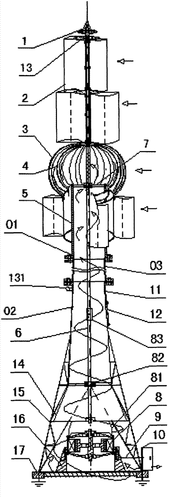
[0025] Embodiment one, attached figure 1 , one Schematic diagram of the structure of a vortex wind turbine.

[0026]As preferred, in the figure: 01. Machine head, 02. Machine base, 03. Extended air duct, 1. Central lightning rod device, 2. The first wind wheel, 3. The second wind wheel, 4. The third wind wheel, 5 .Outlet duct, 6. Extended shaft, 7. First cross bracket, 8. Generator, 9. Lead wire, 10. Control box, 11. Ladder type air duct, 12. Inspection hole door, 13. Or 131. Network Camera, 14. Horn-shaped air inlet, 15. Angle iron or steel pipe support, 16. Whirlwind pier, 17. Concrete foundation at the foot of the iron tower, 81. Reducer or speed increaser, 82. Second cross bracket, 83. Main shaft connection device; wherein, the vortex line indicates the vortex-shaped rise of the air flow in the tube.

Embodiment 2

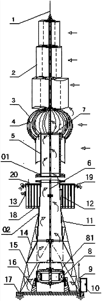
[0027] Embodiment two: attach figure 2 , one Schematic diagram of the structure of a gazebo network wind turbine.

[0028] As a preference, in the figure: 1. Central lightning rod device, 2. The first wind wheel, 3. The second wind wheel, 4. The third wind wheel, 5. Air outlet pipe, 6. Extended shaft, 7. The first cross bracket , 8. Generator, 9. Wire, 10. Control box, 11. Trapezoidal air duct, 12. Inspection hole door, 13. Network camera, 14. Horn-shaped air inlet, 15. Angle iron or steel pipe support, 16. Whirlwind pier, 17. Concrete foundation at the foot of the iron tower, 18. Overlook, 19. Lamp, 20. Wireless transponder, 81. Speed ​​reducer or speed increaser; among them, the central lightning rod device 1 is not equipped with a network camera 13 and lamps 5 For spotlights.

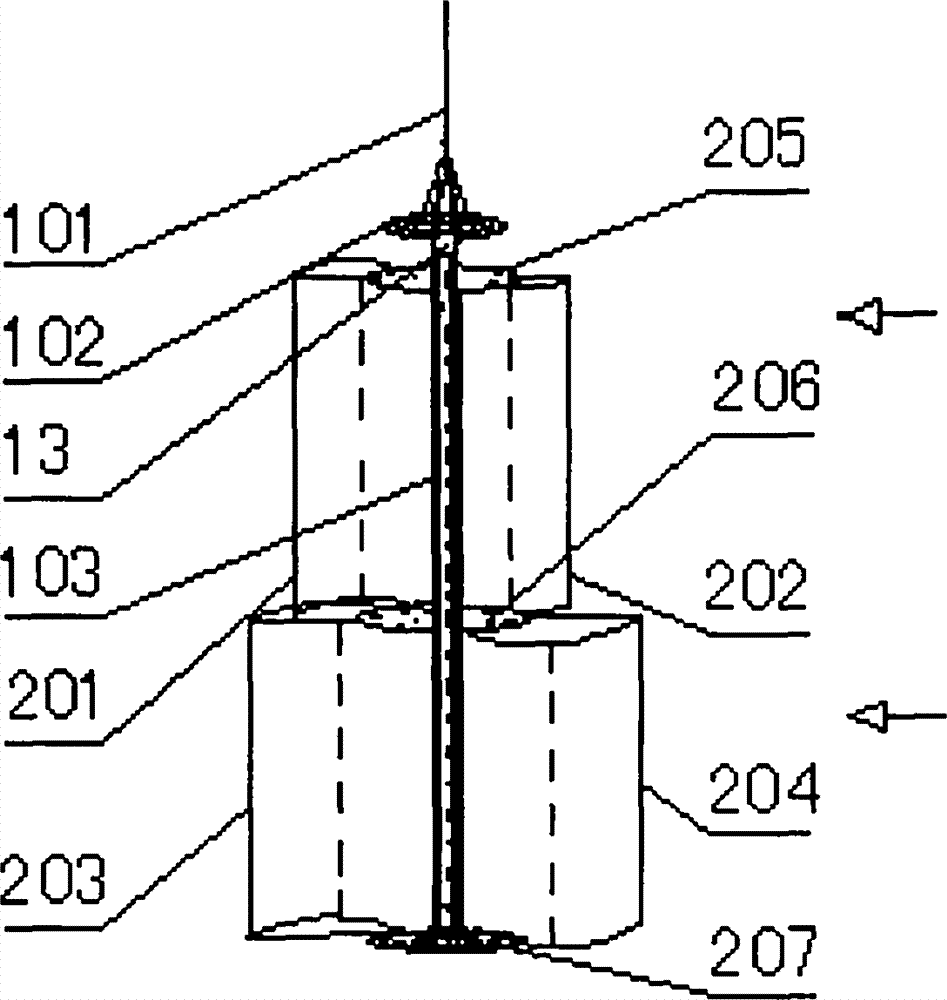
[0029] attached image 3 , Schematic diagram of the structure of the first wind rotor and the central lightning rod device.

[0030] As preferably, among the figure: 13. network camera, 101. l...


PUM


Abstract

The invention relates to a whirlwind driven generator, belonging to the technical field of clean energy sources, namely wind power. The whirlwind driven generator comprises a machine head 01 which is connected to an iron tower type machine stand 02; the output of the generator is modulated by a power supply of a control cabinet and is then connected with a network camera, a wireless transponder and a lamp. The whirlwind driven generator is characterized in that a conical whirlwind pier 16 which consists of a generator body 8, a speed reducer 81 and a footing foundation is arranged in the machine stand; the whirlwind pier is combined with vortex type spherical wind wheels to drive natural air to do vortex whirl around a main shaft and then ascend in an accelerative manner like tornado to continuously enhance torque force and push the wind wheels to rotate from the interior of an air pipe; in the meantime, an external wind source is guided to push the first wind wheel, the second wind wheel, the third wind wheel and the fourth wind wheel to rotate in an all-around manner from the upper part, the middle part and the lower part, and the temperature of an airflow source in a rotation center raises by means of temperature rise of the generator in operation and terrestrial heat temperature; the power generation efficiency is increased manyfold by means of resultant force; the network camera arranged in a central lightning rod device 1 constitutes internet of things together with a mobilephone and a computer and is used for automatically carrying out video monitoring on lightning protection, theft prevention and fire protection in an administrated area so as to further ensure the operation safety.

Description

technical field [0001] The invention relates to a vortex wind generator, which belongs to the technical field of wind power clean energy. Background technique [0002] The utilization of natural wind energy in the prior art is generally limited to wind power generation in the horizontal wind direction, and the wind energy in the vertical direction, upward wind force and horizontal wind direction is not uniformly utilized, and is converted into a vortex wind direction that continuously enhances the rotational torque force like a tornado. Seeking to further promote the rotation of the wind wheel and maximize the power generation efficiency; there are also deficiencies in the facilities of the generator system, and the low-cost wind power supply method is not used to realize the wireless Internet of Things automatic remote video monitoring system, 24-hour video automatic monitoring To manage the operation status of each wind turbine with various methods, and at the same time so...

Claims


Application Information

Patent Timeline
IPC IPC(8): F03D9/00F03D11/04F03D3/02F03D3/04F03D5/00F03D3/06
CPCY02E10/70Y02E10/74
Inventor 陈国祥陈国宝
Owner 杭州博洽智能科技有限公司
Why Eureka
Try Eureka