
Light guide plate and light source module

A light source module, light guide plate technology, applied in the direction of light guide, optics, optical components, etc., can solve the problems of strong beam intensity, uneven bright lines on the side of the light source, etc., achieve large error tolerance, shorten post-processing time, and improve hot spots effect of the problem

Active Publication Date: 2018-04-10
YANGXIN TECH SUZHOU
View PDF9 Cites 0 Cited by
  • Summary
  • Abstract
  • Description
  • Claims
  • Application Information

AI Technical Summary

Problems solved by technology

In this way, the intensity of the beam emitted from the area near the opposite two sides of the light-emitting surface will be too strong, resulting in the surface light source formed by the light source module having uneven side bright lines

Method used


Image

  • Light guide plate and light source module
  • Light guide plate and light source module
  • Light guide plate and light source module

Examples


Embodiment Construction

[0037]The aforementioned and other technical content, features and effects of the present invention will be clearly presented in the following detailed description of a preferred embodiment with accompanying drawings. The directional terms mentioned in the following embodiments, such as: up, down, left, right, front or back, etc., are only referring to the directions of the drawings. Accordingly, the directional terms are used to illustrate and not to limit the invention.

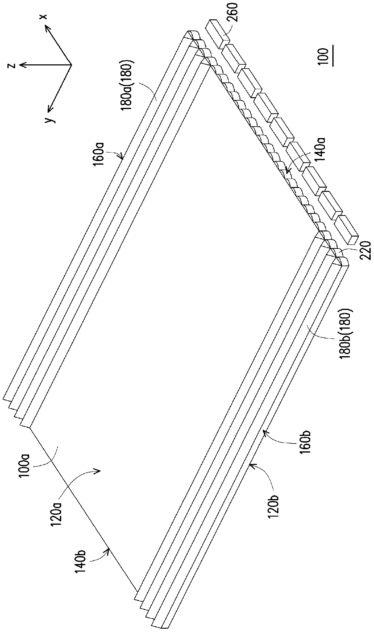
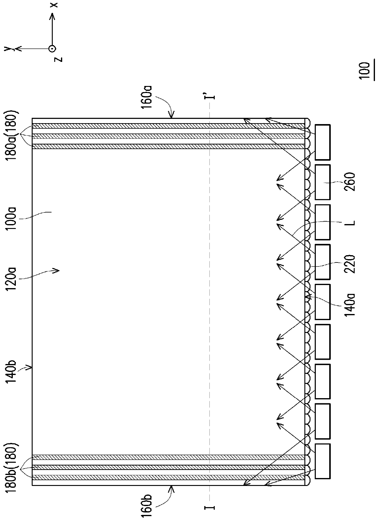
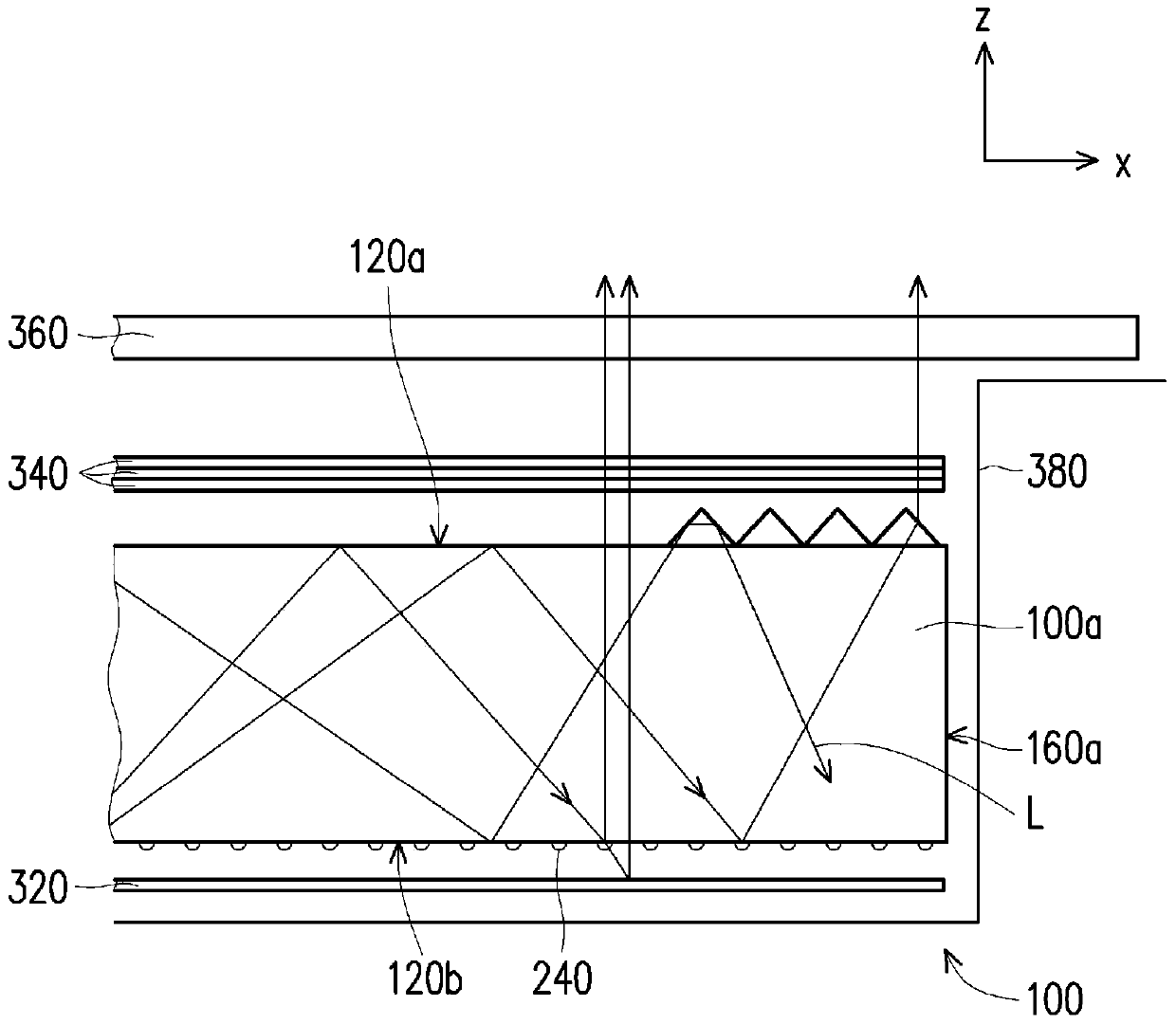
[0038] Figure 1A is a schematic perspective view of a light source module according to an embodiment of the present invention, Figure 1B yes Figure 1A top view of Figure 1C show Figure 1B The cross-section of the light source module of the embodiment along the I-I' line and its partial schematic diagram applied to the liquid crystal display, Figure 1D show Figure 1A The relative positional relationship between the strip microstructure and the light emitting element in the light source module. In ...


PUM


Abstract

The invention discloses a light guide plate and a light source module. The light guide plate comprises a first surface, a second surface opposite to the first surface, an incident surface, an opposite surface opposite to the incident surface, a first side face, a second side face opposite to the first side face, a plurality of end face micro structures and a plurality of strip-shaped micro structures, wherein the incident surface is used for connecting the first surface with the second surface; the opposite surface is used for connecting the first surface with the second surface; the first side face is used for connecting the first surface with the second surface and connecting the incident surface with the opposite surface; the second side face is used for connecting the first surface with the second surface and connecting the incident surface with the opposite surface; the end face micro structures are arranged on the incident surface; the strip-shaped micro structures are only arranged on the first surface and are close to two sides of the first side face and the second side face respectively; and each strip-shaped micro structure extends from one end close to the incident surface to one end close to the opposite face. According to the light guide plate, the hotspot and side edge bright line phenomena of the light source module are solved simultaneously; and the light source module is capable of providing an area light source with excellent uniformity.

Description

technical field [0001] The present invention relates to an optical element and an optical module, and particularly relates to a light guide plate and a light source module. Background technique [0002] With the development of optoelectronic technology, the cold cathode fluorescent lamp (cold cathode fluorescent lamp, CCFL) arranged on the side of the light guide plate in the prior art can be replaced by light-emitting diode (light-emitting diode, LED) light strip (light bar) replaced. Since the light emitting diode has the advantages of long service life, low power consumption, and fast response, the performance and service life of the light source module using the light emitting diode as the light source are also improved. [0003] However, due to the directivity of the light beams emitted by the LEDs, in the area of ​​the light guide plate close to the LEDs, more light beams are received near the optical axis of the LEDs (that is, facing the LEDs) to form a bright area. ...

Claims


Application Information

Patent Timeline
Patent Type & Authority Patents(China)
IPC IPC(8): F21V8/00
CPCG02B6/0016
Inventor 周民俊刘明达郭浩然
Owner YANGXIN TECH SUZHOU
Learn More