
Wall-mounted direct blowing type air processing set

An air handling unit, direct blowing technology, applied in the direction of heating, air conditioning system, air flow control components, etc., can solve the problem of not being able to meet the requirements of indoor environment, increase the initial investment and operation cost of equipment, and directly return to the unit through the return air outlet and other problems, to achieve the effect of simple and compact unit structure, reduce failure points and maintenance costs, and change the installation method and system structure

Inactive Publication Date: 2015-07-15
FERDLIS NEW ENERGY TECH HANGZHOU CO LTD
View PDF7 Cites 3 Cited by
  • Summary
  • Abstract
  • Description
  • Claims
  • Application Information

AI Technical Summary

Problems solved by technology

The equipment room, air duct, static pressure box, etc. will increase the initial investment and operating cost of the equipment, and cannot achieve energy saving and high efficiency.
In addition, at present, when the air duct or fan coil unit is used to supply air directly in the market, the form of top supply and top return is basically adopted. This form of supply and return air can meet the requirements of indoor environment when the floor height of the space is about 3.0m. However, when the floor height of a large space is 5.0m and above, the hot air sent from the top air outlet will float upwards due to the smaller proportion of hot air than cold air under heating conditions, and the hot air cannot reach the area where people are active and passes directly. The phenomenon that the air return port returns to the unit, which cannot meet the requirements of the indoor environment

Method used


Image

  • Wall-mounted direct blowing type air processing set
  • Wall-mounted direct blowing type air processing set
  • Wall-mounted direct blowing type air processing set

Examples


Embodiment Construction

[0020] Below in conjunction with embodiment the present invention is described in further detail:

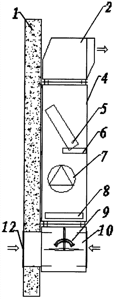
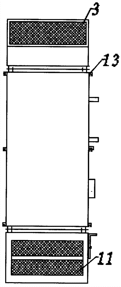
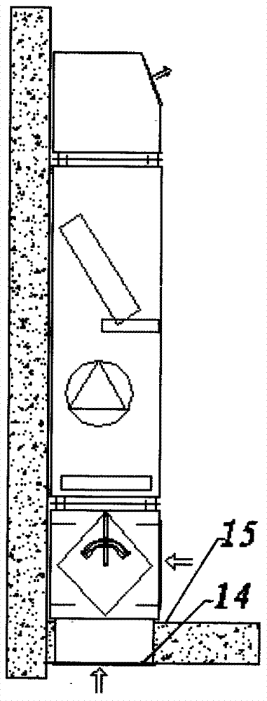
[0021] Such as Figure 1-3 As shown, a wall-mounted direct blowing air handling unit includes an air inlet device, a box body 4 and an air outlet device, and the air inlet device includes an air inlet box 10 arranged at the lower end of the box body 4 and an The tuyere regulating device 9 inside the bellows 10; the box body includes a plate type primary effect filter 8, a blower 7, a cold and hot coil 5, a water tray 6, and an installation hanger 13; the air outlet device includes a The air outlet box 2 on the body 4 upper ends. The air outlet of air outlet box 2 is provided with air supply louver tuyere 3, and the both sides and bottom of air inlet box 10 are provided with fresh air louver tuyere 12, return air louver tuyere 11, bottom louver tuyere 14.

[0022] The installation steps of this unit are as follows:

[0023] 1) Unit box installation: The user selects the unit m...


PUM


Abstract

The invention relates to a wall-mounted direct blowing type air processing set. The wall-mounted direct blowing type air processing set comprises an air inlet device, a box body and an air outlet device, and is characterized in that the air inlet device comprises an air inlet box arranged at the lower end of the box body and an air port adjusting device arranged in the air inlet box, wherein the box body comprises a plate type primary filter, an air feeder, cold and hot coils, a water pan and a mounting rack; and the air outlet device comprises an air outlet box arranged at the upper end of the box body. The wall-mounted direct blowing type air processing set is directly mounted on an indoor wall to save the mounting space, adopts direct air intake and air feed to radically change the mounting mode and the system structure of a terminal set of an air conditioner so as to reduce the initial cost and the operation cost of users to an air conditioning system, and adopts upper air intake and lower air return to combine with multiple air return modes so as to prevent the problem of incapability of satisfying the indoor environment use requirement due to direct air return caused by upward floating of hot air in a mode of top air feed and top air return.

Description

technical field [0001] The invention relates to an air handling unit for air conditioning, in particular to a wall-mounted direct blowing air handling unit. Background technique [0002] At present, most of the air conditioning terminal units on the market are air handling units or fan coil units. The structure of the air handling unit has vertical, horizontal, ceiling and other structures. Among them, the vertical and horizontal units need to be equipped with a machine room, which takes up a lot of space, and these types of structures are generally connected to air ducts. If the air to be processed is mixed with fresh return air, a static pressure box for mixed air is required at the air inlet. The equipment room, air duct, static pressure box, etc. will increase the initial investment and operating cost of the equipment, and cannot achieve energy saving and high efficiency. In addition, at present, when the air duct or fan coil unit is used to supply air directly in the ...

Claims


Application Information

Patent Timeline
Patent Type & Authority Applications(China)
IPC IPC(8): F24F1/00F24F13/14
CPCF24F1/0003F24F13/14
Inventor 赵永平
Owner FERDLIS NEW ENERGY TECH HANGZHOU CO LTD
Learn More