Cable joint cable core temperature inversion method and system based on cable surface temperature

A technology of surface temperature and cable joints, applied in the field of cable joint core temperature inversion method and system, can solve problems such as cable accidents, overheating and burning of accessories, insulation aging, etc., and achieve the effect of ensuring safe operation and reducing failures

Active Publication Date: 2017-06-16
WUHAN UNIV
View PDF5 Cites 1 Cited by
  • Summary
  • Abstract
  • Description
  • Claims
  • Application Information

AI Technical Summary

Problems solved by technology

Due to the characteristics of the cable itself, the accessories (terminals, joints) need to be installed on site after the laying is completed. The production is affected by the adverse factors of the site environment and the limitation of the production process, and the crimping quality of the cable intermediate joint can only be tested during operation.
The longer its running time, the more prone to overheating and burn-through accidents
At the same time, after a period of high current (overload) operation, overheating and oxidation often occur at the crimping point, which gradually increases the contact resistance and the temperature of the contact point, aging the insulation, and eventually causing damage to the insulation layer and causing accidents. occur
However, the existing above-mentioned technologies are mainly an indirect monitoring of the cable aging state, and cannot directly provide timely early warning of power cable faults, which may easily cause cable accidents.

Method used


Image

  • Cable joint cable core temperature inversion method and system based on cable surface temperature
  • Cable joint cable core temperature inversion method and system based on cable surface temperature
  • Cable joint cable core temperature inversion method and system based on cable surface temperature

Examples


Embodiment Construction

[0043] The technical solutions of the present invention will be further described below in conjunction with the accompanying drawings and specific embodiments.

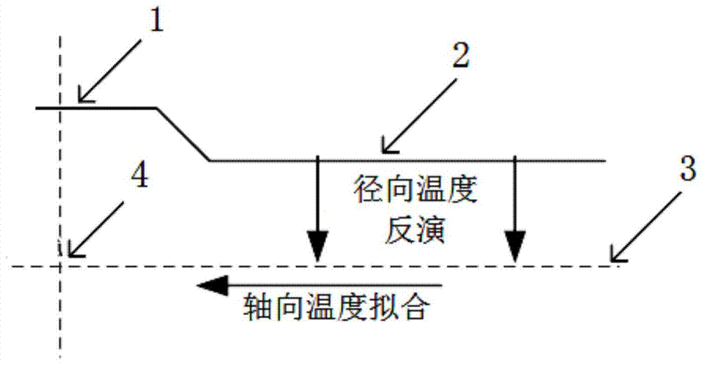
[0044] figure 1 It is a schematic diagram of the principle of the present invention, from which it can be seen that the present invention is characterized in that the temperature of the cable core contact point (4) at the cable joint is obtained by combining radial temperature inversion and axial temperature fitting. The so-called cable core contact point refers to the contact surface of the two cable cores inside the cable joint, where the temperature is the highest due to the relatively large contact resistance.

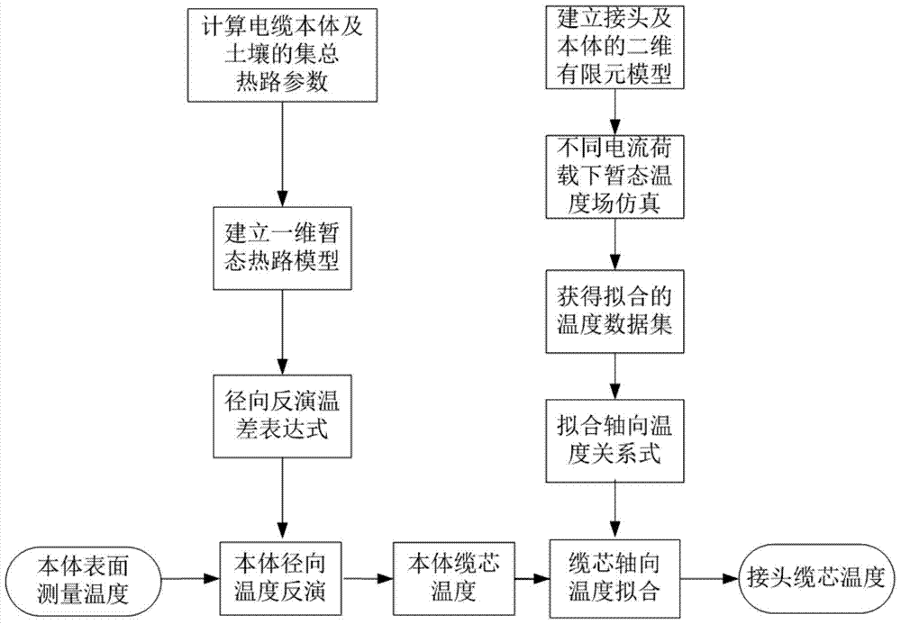
[0045] figure 2 It is a specific flow chart of the present invention, mainly including two parts: radial temperature inversion and axial temperature fitting. Radial temperature inversion means: according to the structure and material parameters of the cable body, as well as the soil structure and material...


PUM


Abstract

The invention provides a cable joint core temperature inversion method and system based on the cable surface temperature, comprising: step 1, performing radial temperature inversion according to the one-dimensional transient thermal circuit model of the cable and the surface temperature measurement point temperature of the cable body Step 2: Use the finite element temperature field simulation method to construct a two-dimensional cable temperature field simulation model, and simulate the cable core contact point and cable core at different loading currents and different times The transient temperature of the fitting point is obtained to obtain the transient temperature simulation data set; step 3, taking the transient temperature of the cable core contact point as the independent variable and the transient temperature of the cable core fitting point as the dependent variable, the transient temperature simulation data set Perform fitting to obtain the cable core axial temperature function; step 4, combine the cable core fitting point inversion transient temperature and the cable core axial temperature function to obtain the cable core contact point temperature. The present invention utilizes the surface temperature of the cable body to obtain accurate cable core contact point temperature through inversion and fitting, which is simple and convenient.

Description

technical field [0001] The invention belongs to the technical field of on-line monitoring for disaster prevention and mitigation of power cables, and in particular relates to a cable joint cable core temperature inversion method and system based on the surface temperature of the cable. Background technique [0002] Power cable is an indispensable and important part of the power system and undertakes the heavy responsibility of power transmission. Due to the aging of the cable joint insulation, the partial discharge current in some areas becomes larger, especially in the case of high load, which causes a sharp temperature rise inside the cable joint, and the resulting explosion of the joint poses a threat to the safe and stable operation of the transmission line. The on-line monitoring technology for disaster prevention and mitigation of power cables needs to be improved urgently. At present, the commonly used on-line monitoring technologies for power cables at home and abro...

Claims


Application Information

Patent Timeline
Patent Type & Authority Patents(China)
IPC IPC(8): G01K13/00G01K1/143
Inventor 阮江军刘超黄道春
Owner WUHAN UNIV
Why Eureka
Try Eureka