
Mechanical wear testing device

A technology of mechanical wear and test device, applied in the field of machinery, can solve the problems of affecting the accuracy of wear test, taking a long time for the test, and unable to ensure the ratio of sand and liquid, so as to improve the horizontal alignment effect, improve the test effect, and improve the detection effect of effect

Active Publication Date: 2015-07-15
TIANJIN JINGPU TECH
View PDF12 Cites 1 Cited by
  • Summary
  • Abstract
  • Description
  • Claims
  • Application Information

AI Technical Summary

Problems solved by technology

[0003] First of all, using the existing nozzle structure, when the diameter of the air nozzle needs to be set to 1.3mm, and the working pressure is guaranteed, if the flow rate of the spray liquid proposed according to the standard is formed on the wear surface at a distance of 380mm±10mm from the nozzle, The area requirements of the fan-shaped spray stream are obviously impossible for ordinary sandblasting machines
[0004] Secondly, when mixing silica sand and water, since the specific gravity of silica sand is greater than 1.6 and the specific gravity of water is 1, the silica sand sinks to the bottom of the water. According to the general liquid mixing method, rotate the mixed liquid or use a motor to rotate the stirring paddle, part of the silica sand floats, while Most of the silica sand will pile up new sand bags along the direction of the stirring paddle rotation, and the ratio of sand to water cannot be guaranteed, so there is no way to ensure that the ratio of the sprayed sand liquid is 25g of silica sand per liter of water, which directly affects The accuracy of the wear test
[0005] Furthermore, in order to ensure that the sample sheet and the sample are set flush, that is, to ensure that the top surfaces of the samples in each form are on the same horizontal plane, it is necessary to measure the distance between the upper surface and the nozzle multiple times, resulting in a long test time.

Method used


Image

  • Mechanical wear testing device
  • Mechanical wear testing device
  • Mechanical wear testing device

Examples


Embodiment Construction

[0025] The present invention will be described in further detail below in conjunction with the accompanying drawings and specific embodiments. It should be understood that the specific embodiments described here are only used to explain the present invention, not to limit the present invention.

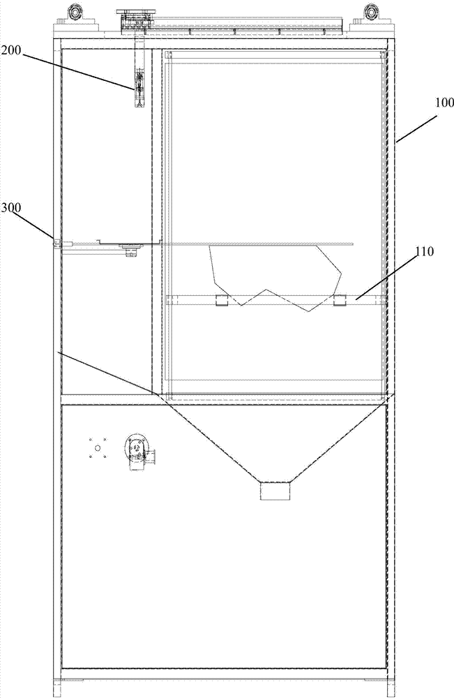
[0026] Such as figure 1 As shown, the mechanical wear test device of the present invention includes a cabinet 100, which can be driven to move up and down and is arranged in the cabinet to carry a bracket 110 for carrying samples, which is vertically arranged on the upper part of the inner space of the cabinet and can be driven left and right The spray gun 200 used for the mechanical wear test of the reciprocating plastic light distribution mirror is horizontally arranged on one side of the cabinet to assist the laser pointer 300 of the flush setting of the sample, and is arranged on the outside of the cabinet to provide sand to the spray gun. A water-mixed sand-water mixing agitator...


PUM


Abstract

The invention discloses a mechanical wear testing device. The mechanical wear testing device comprises a cabinet body, a bracket, a spray gun, a laser pen, and a sand and water mixing and stirring device, wherein the bracket is driven to be arranged in the cabinet body in a vertical moving mode and is used for bearing a sample; the spray gun is vertically arranged in the upper part of the internal space of the cabinet body and is driven to move left and right in a reciprocating mode for the mechanical wear testing for a plastic lens; the laser pen is horizontally arranged at one side of the cabinet body and is used for assisting in the flush arrangement of a sample; the sand and water mixing and stirring device is arranged at one side outside the cabinet body and is used for providing mixed sand and water for the spray gun. The mechanical wear device is used for sand spray wearing, and meanwhile is used for adjusting the height of the liquid level of the sand and water mixing and stirring device, so that the working condition of the spray gun can be ensured effectively, and the testing effect is improved when the sand spray condition is not changed in the testing process; moreover, the laser pen is arranged so as to improve the sample and the integral horizontal alignment effect; the testing conditions of samples are the same, and the detection effect is improved.

Description

technical field [0001] The invention relates to the technical field of machinery, in particular to a mechanical wear test device. Background technique [0002] The mechanical wear test is a sandblasting test process at a fixed point or area according to certain requirements. For example, when performing a mechanical wear test on the photometric mirror of an automotive lamp, the test requirements of the automotive lamp standard in my country completely follow the EU ECE standard and the national standard. GB 4599-2007 "Filament Bulb Headlamps for Automobiles" requires the following mechanical wear test methods in Appendix E: the spray gun should be equipped with a nozzle with a diameter of 1.3mm, when the working pressure is At Mpa, the flow rate of the spray liquid is (0.24±0.02)1 / min. And on the wear surface at a distance of 380mm±10mm from the nozzle, form a jet flow area with a diameter of 170mm±50mm scattered, and place the headlamp on the same horizontal plane in this ...

Claims


Application Information

Patent Timeline
Patent Type & Authority Applications(China)
IPC IPC(8): G01N3/56
Inventor 高岩苏畅王子樑孙骏
Owner TIANJIN JINGPU TECH
Learn More