Circulating cooling device for wind power generation

A technology of circulating cooling and wind wheel, applied in wind power generation, wind turbines, engines, etc., can solve the problems of motor heating, engine room temperature rise, damage, etc., to extend the service life, reduce the impact of direct blowing, and improve reliability. Effect

Active Publication Date: 2021-06-29
中顺元通新能源集团有限公司
View PDF4 Cites 0 Cited by
  • Summary
  • Abstract
  • Description
  • Claims
  • Application Information

AI Technical Summary

Problems solved by technology

Wind power generation devices generally include wind rotors (that is, blades, main shafts, yaw mechanisms, pitch mechanisms, etc.), speed increasers, generators, control cabinets, frequency converters, brakes, yaw mechanisms, pitch mechanisms, etc. The functions of wind turbines are becoming more and more comprehensive, and there are more and more functional components such as various mechanisms, devices, and components attached to them; The temperature of the warehouse rises, which affects the normal operation and service life of each component. In severe cases, the wind turbine must be shut down to cool down, or even damaged
In order to realize the heat dissipation of the machine cabin, the currently commonly used method is to install an air-cooling device inside the machine room, but the traditional air-cooling device is driven by a motor, which fails to give full play to the cooling and cooling effect of the high-altitude air flow; at the same time, the motor itself will generate heat. Definitely reduces the overall cooling effect

Method used


Image

  • Circulating cooling device for wind power generation
  • Circulating cooling device for wind power generation
  • Circulating cooling device for wind power generation

Examples


Embodiment Construction

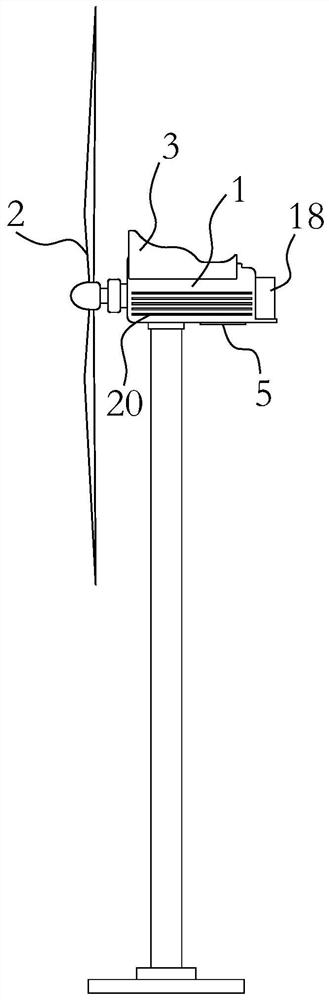
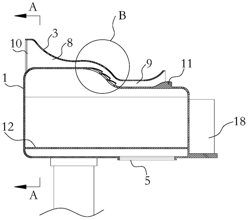
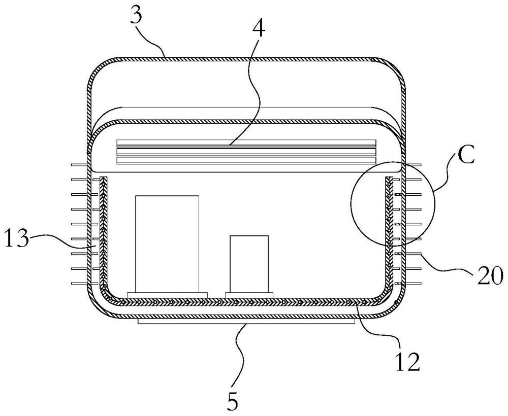
[0023] like Figure 1-6 As shown, a circulating cooling device for wind power generation is mainly used to cool down the overall temperature of the cabin 1 of the wind power generation equipment, so as to ensure that the functional equipment inside the cabin 1 has a stable working condition and prolong its service life. The present invention includes a machine room 1 installed on an iron tower, the front end of the machine room 1 is provided with a wind wheel 2, and the front end is also the windward end of the machine room 1, that is, figure 2 in the left end. The upper part of the cabin 1 is fixedly provided with an air collection cover 3, which is used to converge the high-altitude high-speed airflow on the top surface of the cabin 1 to increase the wind speed. An ejection channel is formed between the air collection cover 3 and the top surface of the machine compartment 1, and the high air flow flows in the ejection channel. The top of the machine compartment 1 is also ...


PUM


Abstract

The invention relates to the technical field of wind power generation. The invention aims to provide a circulating cooling device for wind power generation. The circulating cooling device for wind power generation comprises an engine room installed on an iron tower, a wind wheel is arranged at the front end of the engine room, a wind gathering cover is fixedly arranged on the upper portion of the engine room, and an injection channel is defined between the wind gathering cover and the top face of the engine room; and a heat dissipation opening communicating with the injection channel is further formed in the top of the engine room, and a cold air inlet is formed in the bottom of the engine room. According to the circulating cooling device for wind power generation, high-altitude high-speed air flow can be fully utilized to dissipate heat inside the engine room, hot air inside the engine room is ejected and exhausted, heat deposition in the engine room is prevented, the heat dissipation reliability of the engine room is improved, the working condition stability of functional equipment inside the engine room is guaranteed, and the service life of the functional equipment is prolonged.

Description

technical field [0001] The invention relates to the technical field of wind power generation, in particular to a circulating cooling device for wind power generation. Background technique [0002] Wind power generation uses wind power to drive windmill blades to rotate, and then increases the speed of rotation through a speed increaser to drive generators to generate electricity. Compared with traditional thermal power, nuclear power and other power generation methods, wind power has huge advantages such as cleanness, environmental protection and renewable, because of these advantages. In recent years, wind power generation is forming an upsurge in the world. Wind power generation devices generally include wind rotors (that is, blades, main shafts, yaw mechanisms, pitch mechanisms, etc.), speed increasers, generators, control cabinets, frequency converters, brakes, yaw mechanisms, pitch mechanisms, etc. The functions of wind turbines are becoming more and more comprehensiv...

Claims


Application Information

Patent Timeline
IPC IPC(8): F03D80/60F03D80/80
CPCF03D80/60F03D80/88Y02E10/72
Inventor 董占武
Owner 中顺元通新能源集团有限公司
Why Eureka
Try Eureka