Assembly tooling for diesel engine valve collet

A diesel engine and valve lock clip technology, which is applied to assembly machines, manufacturing tools, metal processing equipment, etc., can solve problems such as low assembly efficiency, affecting the smooth operation of valves, and poor coaxiality, and achieve the effect of improving assembly work efficiency

Active Publication Date: 2014-04-16
重庆小康动力有限公司
View PDF7 Cites 0 Cited by
  • Summary
  • Abstract
  • Description
  • Claims
  • Application Information

AI Technical Summary

Problems solved by technology

[0004] Due to the high cylinder pressure of the diesel engine, the valve lock clip has two axially separated lobes, and three ring-shaped protrusions are formed on the inner surface, and three ring grooves corresponding to the ring-shaped protrusions are formed on the corresponding part of the valve push rod. , the annular protrusion is embedded in three ring grooves to fix the valve lock clamp in the axial direction. At the same time, the upper seat of the valve spring is overlaid on the valve lock clamp to fix the two petals in the radial direction to avoid scattering; the structure design of the three grooves has a better positioning effect , suitable for the working conditions of diesel engines, but the installation is more difficult. If the commonly used method of pressing into the end of the valve stem together with the spring upper seat is adopted, the outer diameter of the fully installed lock clip after being expanded by the end of the valve ejector rod is much larger than Due to the diameter of the taper hole on the upper seat of the spring, the two-valve valve lock clip cannot be accurately installed in the lock clip groove at the end of the valve stem, resulting in low assembly reliability and poor coaxiality of the lock clip, which affects the smooth operation of the valve; and, assembly less efficient

Method used


Image

  • Assembly tooling for diesel engine valve collet
  • Assembly tooling for diesel engine valve collet
  • Assembly tooling for diesel engine valve collet

Examples


Embodiment Construction

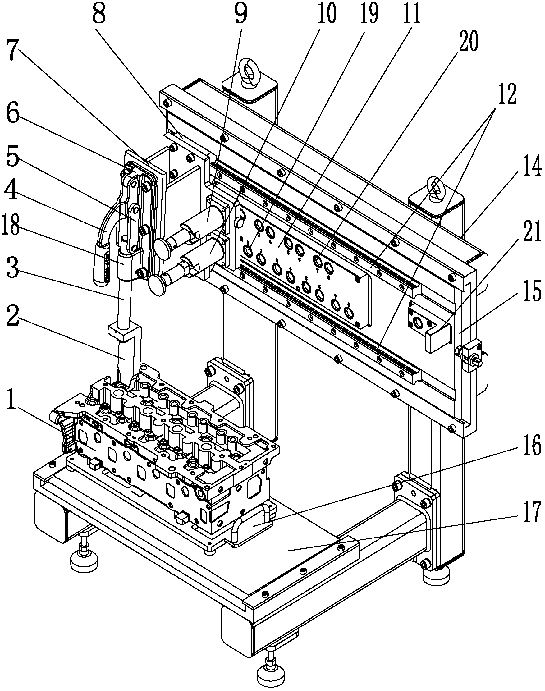
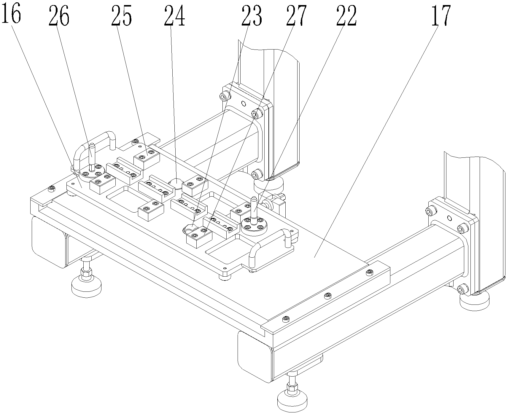
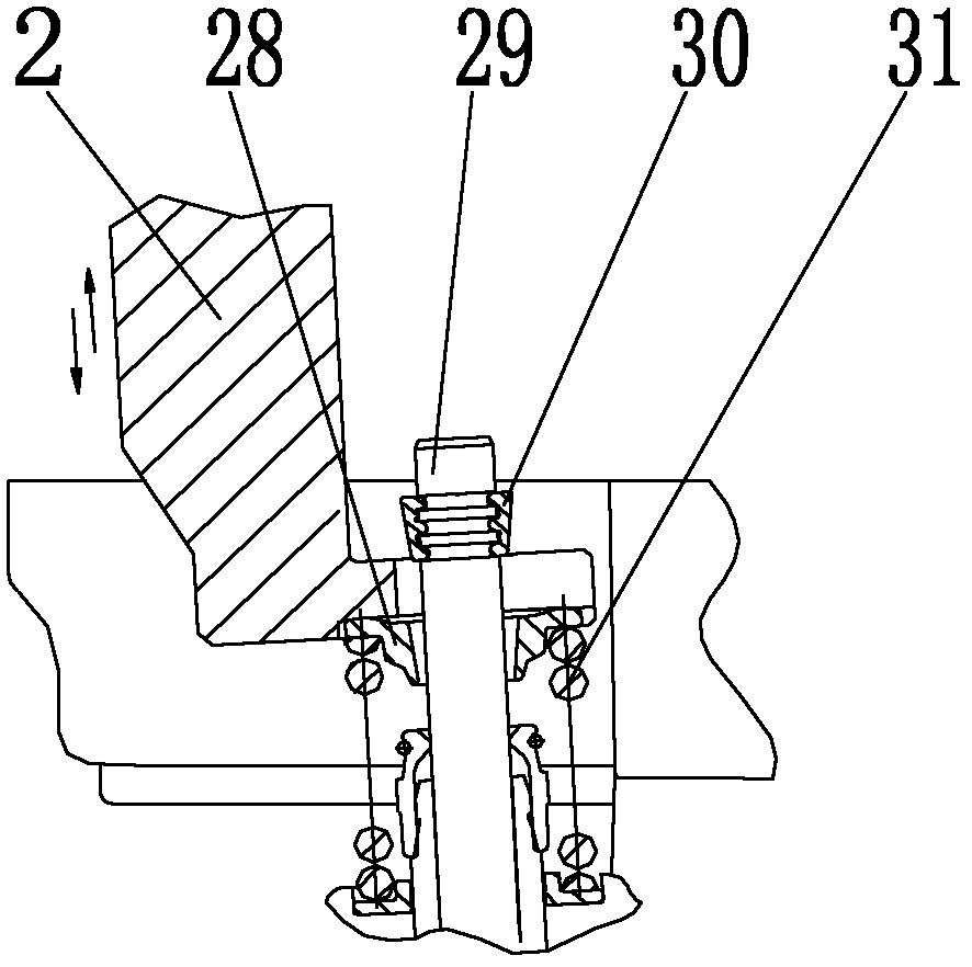
[0023] figure 1 It is a structural schematic diagram of the present invention, figure 2 It is a schematic diagram of the structure of the base of the present invention, image 3 It is a structural schematic diagram of the installation process of the present invention, Figure 4 It is a horizontal guide rail and a slide block with a cross-sectional structure, as shown in the figure: the diesel engine valve lock clip assembly tool of the present embodiment includes a fork-shaped pressure head 2, and the opening of the fork-shaped pressure head 2 is smaller than that of the valve spring upper seat 28. The transverse dimension is used to press down the upper seat 28 of the valve spring. The opening of the fork head 2 is at least larger than the outer diameter of the rod section of the valve ejector rod 29 for installing the valve lock clip 30. The fork head 2 is used to press down the upper seat 28 of the valve spring. And exposed valve push rod 29 is used to install the end of...


PUM


Abstract

The invention discloses an assembly tooling for a diesel engine valve collet, which comprises a forked pressure head, wherein an opening of the forked pressure head is smaller than a horizontal size of a valve spring upper base and used for pressing down the valve spring upper base, and the opening of the forked pressure head is at least larger than a stem outer diameter of a valve stem for installing the valve collet. In use, a pressure towards the valve spring upper base is applied to the forked pressure head, the spring is compressed and three ring slots are exposed, three annular bulges on two flaps of the valve collet are embedded in three rings and the valve collet is formed as one piece, the forked pressure head releases the valve spring upper base, and the valve spring upper base is externally sleeved on the valve collet outer circle under the spring action. With the assembly tooling, positioning and assembling can be rapidly carried out; the coaxiality of the valve collet, the valve spring upper base and the valve stem can be ensured; the direction of the spring force can be made to meet the stem movement requirement; the assembled valve system can be ensured to accord with the operating condition of the diesel engine; the working efficiency in assembly can be increased; and the assembly tooling is especially suitable for the assembling requirement of batch production of multi-valve diesel engines.

Description

technical field [0001] The invention relates to an auxiliary device for assembly of mechanical equipment, in particular to an assembly auxiliary device for a diesel engine valve assembly. Background technique [0002] The valve of the engine is the passage for the gas in and out of the combustion chamber. The opening and closing of the valve is realized by reciprocating movement during work, and it must bear great alternating and impact loads during the movement. In the prior art, the closing of the valve is accomplished by the valve spring, and the spring transmits the pre-tightening force for closing the valve through the valve spring seat, and the valve lock clip is a part for limiting the upper seat of the valve spring. Ensure the pre-tightening force of the spring used to close the valve; since the main function of the valve lock clip is to move the upper seat of the valve spring to the upper limit, the installation structure of the valve lock clip has better coaxiality...

Claims


Application Information

Patent Timeline
Patent Type & Authority Patents(China)
IPC IPC(8): B23P21/00
Inventor 李剑斌李金印王艳朋
Owner 重庆小康动力有限公司
Why Eureka
Try Eureka