

Rotor fault diagnosis method giving comprehensive consideration to current and voltage of motor
A technology of motor current and comprehensive consideration, which is applied in the direction of motor generator testing, measurement of electricity, and measurement of electrical variables. It can solve the problems of motor controller parameter influence and no quantitative index, and achieve online rotor fault diagnosis and large-scale practical meaning effect
- Summary
- Abstract
- Description
- Claims
- Application Information
AI Technical Summary
Problems solved by technology
Method used
Image

Examples
Embodiment 1
[0031] Embodiment 1: This embodiment deduces the amplitude I and the initial phase of the fault severity index k and the current fundamental wave component Amplitude U and initial phase of voltage fundamental component Current fundamental wave component initial phase The amplitude I of the left frequency current component l and initial phase The amplitude U of the left frequency voltage component l and, the initial phase of the left frequency voltage component The relationship between, specifically:
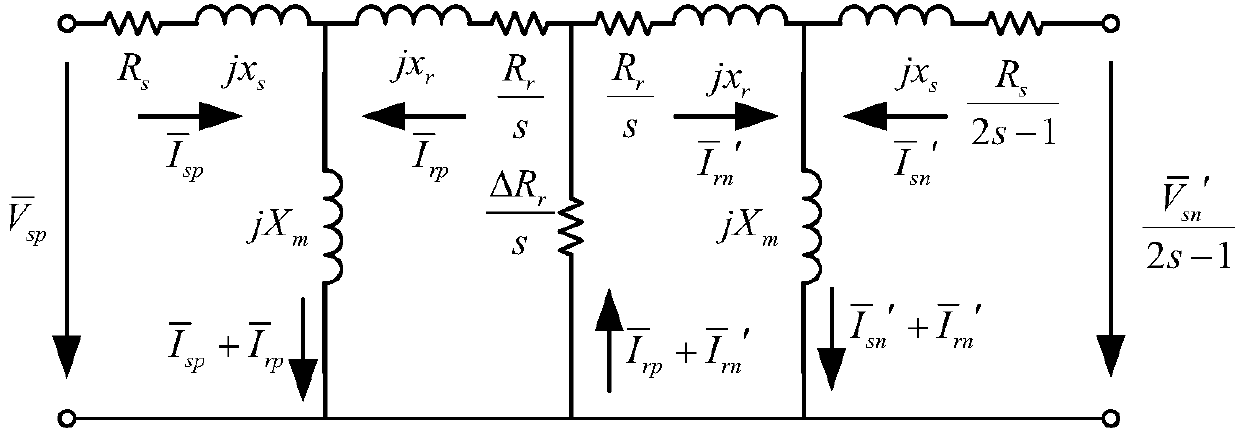
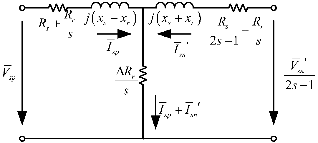
[0032] When the motor rotor is broken, the model on the motor rotor coordinate system is
[0033]
[0034] where u sd , u sq is the voltage of motor stator d-axis and q-axis, i sd i sq i rd i rq are the d-axis and q-axis currents of the stator and rotor, respectively, R s is the motor stator resistance, L s , L m , L r is the stator inductance, excitation inductance and rotor inductance of the motor, ω is the rotational angular velocity of the motor rotor, ...
Embodiment 2
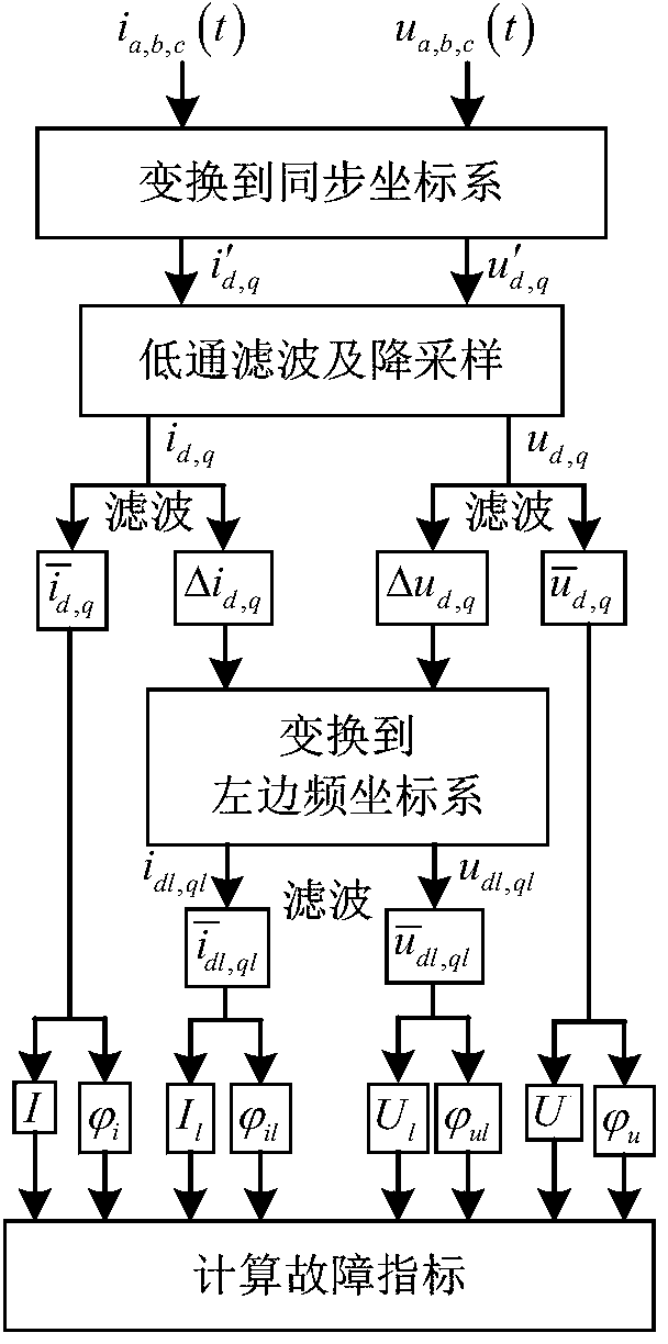
[0063] Embodiment 2: In this embodiment, the relational formula derived in Embodiment 1 is used to diagnose the fault of the rotor, and the steps are as follows image 3 Shown:
[0064] (1) Collect the current and voltage signals of the motor. In this example, the sampling frequency of the voltage and current signals is the same as the time of the current loop, which is 8kHz (ie 125us). The current signal is collected by the current sensor. For Y-connected motors, the sum of the three-phase currents is always zero. Therefore, the third phase current of the motor can be obtained only by measuring the two phase currents. Note that the three-phase current signals are respectively i a , i b , i c ; In the present embodiment, the three-phase stator voltage can be approximately considered as the given voltage in the controller, therefore, it can be obtained by the voltage given signal of the DSP processor, and the three-phase voltage signals are respectively u a , u b , u c ...
PUM
 Abstract
Description
Claims
Application Information