Chip packaging structure and manufacture method thereof

A technology of chip packaging structure and manufacturing method, applied in semiconductor/solid-state device manufacturing, semiconductor/solid-state device parts, semiconductor devices, etc., can solve problems such as unsatisfactory, large package resistance, thick package thickness, etc., to avoid virtual soldering , Reduce package resistance and improve reliability

Inactive Publication Date: 2015-07-15
HEFEI SMAT TECH CO LTD
View PDF5 Cites 9 Cited by
  • Summary
  • Abstract
  • Description
  • Claims
  • Application Information

AI Technical Summary

Problems solved by technology

[0003] Although this traditional wire bonding packaging method has a relatively mature process and a large output, it will inevitably lead to a large packaging resistance because it needs to use slender metal leads to lead out the electrodes on the chip surface. In addition, the metal leads and False soldering is pr

Method used


Image

  • Chip packaging structure and manufacture method thereof
  • Chip packaging structure and manufacture method thereof
  • Chip packaging structure and manufacture method thereof

Examples


Embodiment Construction

[0055] Hereinafter, the present invention will be described in more detail with reference to the accompanying drawings. In the various drawings, the same components are denoted by similar reference numerals. For the sake of clarity, various parts in the drawings have not been drawn to scale. Also, some well-known parts may not be shown. For simplicity, the structure obtained after several steps can be described in one figure. In the following, many specific details of the present invention, such as the structure, material, size, process and technique of each constituent part, are described for a clearer understanding of the present invention. However, the invention may be practiced without these specific details, as will be understood by those skilled in the art.

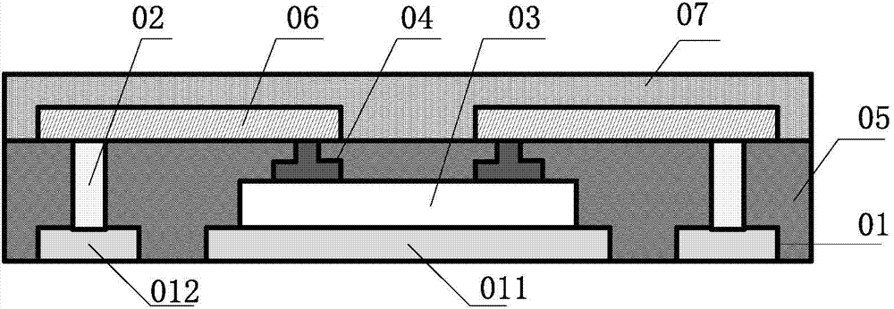
[0056] figure 1 It is a schematic cross-sectional structure diagram of a chip packaging structure provided according to an embodiment of the present invention.

[0057] Such as figure 1 As shown, in this embod...


PUM


Abstract

The invention provides a chip packaging structure and a manufacture method thereof. The chip packaging structure comprises a first pin, a first conductive post positioned on the first pin, and a second pin positioned on a second conductive post and electrically connected with the second conductive post and a first electric connecting body on a chip active surface, wherein an electrode bonding pad on the chip active surface is led out through a conductive path comprising the first electric connecting body, the second pin, the first conductive post and the first pin, and finally the electric connection between a chip and an external circuit is realized through the first pin. The mode for leading out the electrode can effectively reduce packaging resistance, does not need solder for welding, can avoid the phenomenon of pseudo soldering, improves the chip packaging reliability, and effectively reduces the chip packaging thickness.

Description

technical field [0001] The invention relates to the technical field of chip packaging, in particular to a chip packaging structure and a manufacturing method thereof. Background technique [0002] In the traditional chip front-mount package structure, the non-active surface of the chip is adhered to the chip carrier plate of the lead frame, and the electrodes on the active surface of the chip are electrically connected to the pins around the carrier plate through metal leads, so that the The electrodes on the active surface of the chip are drawn out to connect with external circuits. [0003] Although this traditional wire bonding packaging method has a relatively mature process and a large output, it will inevitably lead to a large packaging resistance because it needs to use slender metal leads to lead out the electrodes on the chip surface. In addition, the metal leads and False soldering is prone to occur between the pads of the chip, which is not conducive to ensuring ...

Claims


Application Information

Patent Timeline
IPC IPC(8): H01L23/31H01L23/492H01L23/48H01L21/50H01L21/60
CPCH01L2224/24H01L23/3107H01L23/3135H01L23/49537H01L23/5389H01L24/82H01L2924/00014H01L2224/32225H01L2224/32245H01L21/568H01L24/19H01L24/24H01L24/29H01L24/32H01L24/73H01L24/92H01L2224/04105H01L2224/12105H01L2224/131H01L2224/16227H01L2224/291H01L2224/2919H01L2224/48227H01L2224/73267H01L2224/83851H01L2224/92244H01L2924/15313H01L24/16H01L24/48H01L23/49575H01L24/81H01L2224/81191H01L25/117H01L2224/45099H01L2224/45015H01L2924/207H01L2224/85399H01L2224/05599H01L2924/014H01L25/0655H01L24/11H01L25/50H01L2224/16245H01L2224/48245H01L2224/81801H01L2224/16225
Inventor 谭小春
Owner HEFEI SMAT TECH CO LTD
Why Eureka
Try Eureka