Electrically-driven working apparatus

A kind of operating equipment and electric technology, which is applied in the direction of electric vehicles, mechanical equipment, current collectors, etc., can solve the problems of cutting off power supply and battery deterioration, and achieve the effect of reducing the failure rate

Active Publication Date: 2015-07-15
MAKITA CORP
View PDF4 Cites 1 Cited by
  • Summary
  • Abstract
  • Description
  • Claims
  • Application Information

AI Technical Summary

Problems solved by technology

[0005] Therefore, in the event of a short-circuit fault in the cut-off element, the power supply path cannot be cut off by the a

Method used


Image

  • Electrically-driven working apparatus
  • Electrically-driven working apparatus
  • Electrically-driven working apparatus

Examples


Embodiment Construction

[0046] Hereinafter, embodiments to which the present invention is applied will be described with reference to the drawings.

[0047] However, the present invention is not limited to the following embodiments, as long as it belongs to the technical scope of the present invention, various methods can of course be adopted.

[0048] [The overall structure of the electric tool]

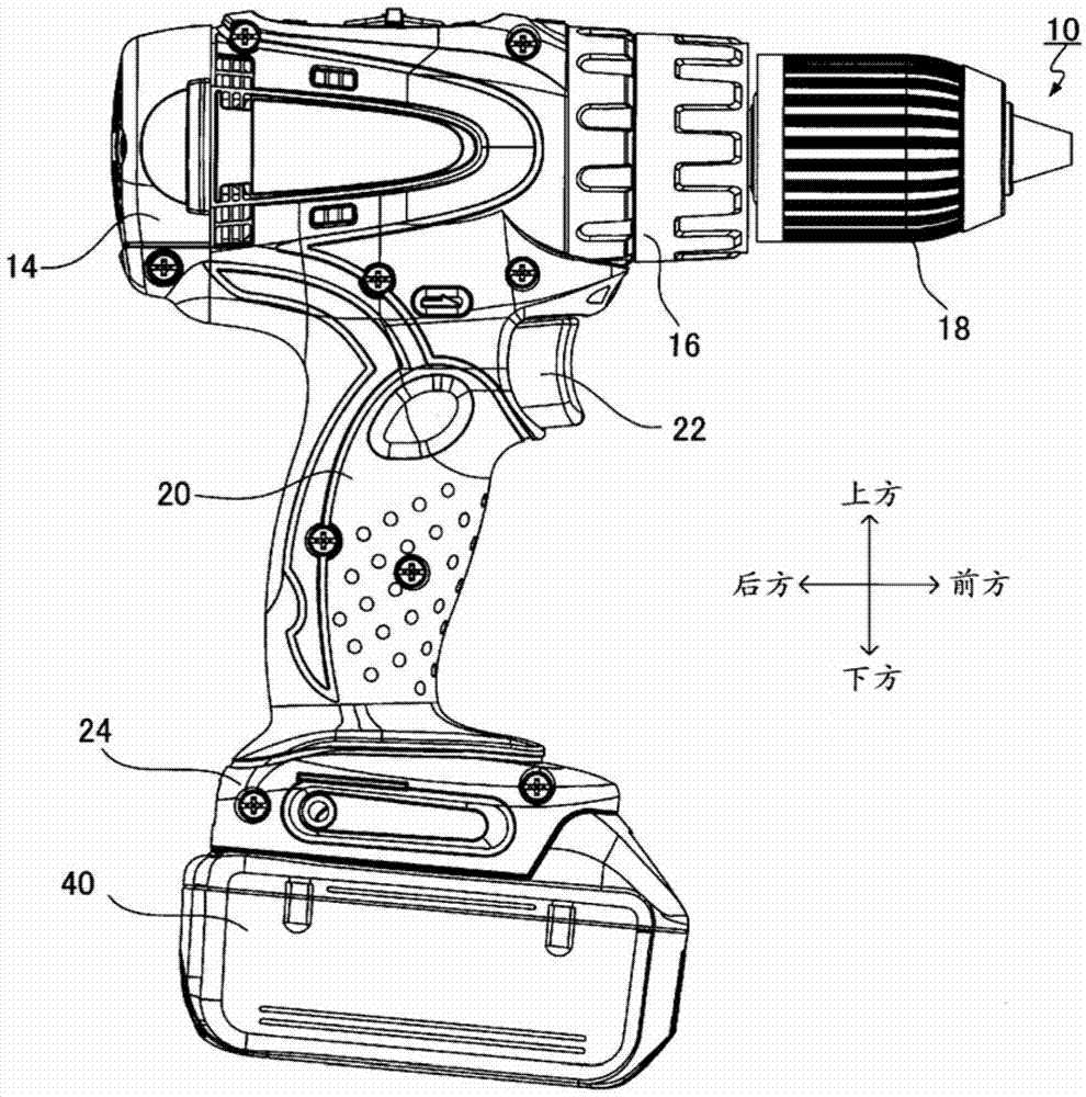
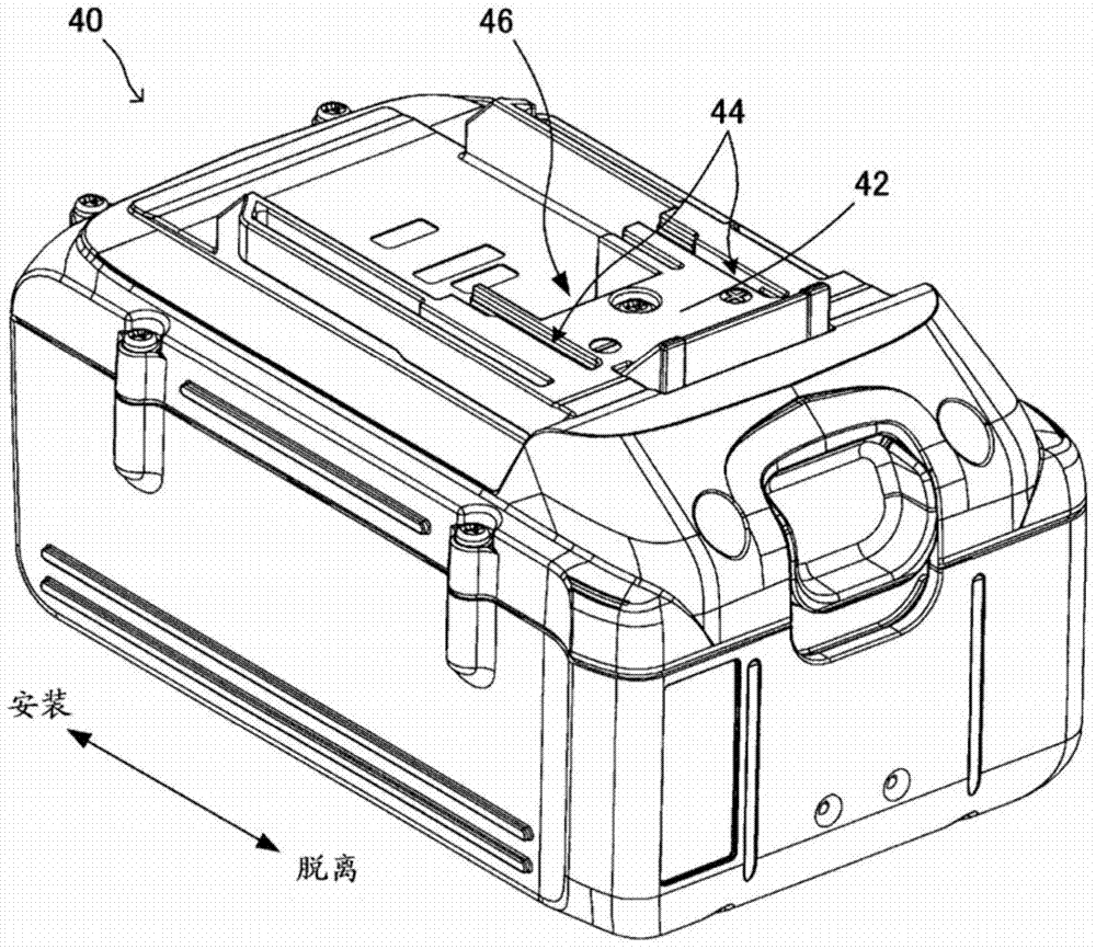
[0049] Such as figure 1 As shown, the power tool of the present embodiment includes a power tool body 10 configured as a so-called drive drill, and a battery pack 40 that is detachably attached to the power tool body 10 and supplies power to the power tool body 10.

[0050] The power tool main body 10 includes: a motor housing 14, a gear housing 16 located in front of the motor housing 14, a drill chuck 18 located in front of the gear housing 16, and a handle located below the motor housing 14. Handle 20.

[0051] The motor housing 14 houses a motor 30 that generates a driving force to rotate the drill chuck 18 (re...


PUM


Abstract

An electrically-driven working apparatus in one aspect of an embodiment of the present disclosure comprises: a battery; an abnormality detection unit; a power supply path; a first disconnection unit; a second disconnection unit; and a control unit. The control unit activates the first disconnection unit to disconnect the power supply path if either of an overload or an over discharge of the battery is detected by the abnormality detection unit, and subsequently determines whether discharge from the battery has stopped after activating the first disconnection unit, and activates the second disconnection unit to disconnect the power supply path if discharge from the battery has not stopped.

Description

Technical field [0001] The present invention relates to an electric work machine equipped with an actuator that operates by receiving power supply from a battery. Background technique [0002] Electric working equipment such as electric tools and electric dust collectors are equipped with a protection function that prevents battery degradation by cutting off the power supply path from the battery to the actuator if an overload or over-discharge of the battery is detected during their operation ( For example, refer to Patent Document 1 etc.). [0003] Patent Document 1: JP 2012-135849 A [0004] However, in the conventional electric work equipment, when an overload or overdischarge of the battery is detected, only the cutoff element (FET in Citation 1) provided in the power supply path from the battery to the actuator is changed to Cut off state. [0005] Therefore, in the case of a short-circuit failure of the interrupting element, the power supply path cannot be interrupted by the ...

Claims


Application Information

Patent Timeline
IPC IPC(8): H02J7/00F16K15/14
CPCH02J7/0063H02J7/0031H02H1/06H02H7/18H02J2007/004B25F5/00H02H3/202H02J7/00306H02J7/00714H02J7/007182H02J7/007194H02H3/044H02H3/05Y02E60/10
Inventor 上杉纮生梅村卓也远藤隆良野田将史
Owner MAKITA CORP
Why Eureka
Try Eureka