Electrical discharge machining apparatus

A technology of electrical discharge machining and power supply, which is applied in the direction of electric processing equipment, metal processing equipment, circuits, etc., can solve the problem of difficult discharge and other problems, achieve the effect of preventing short circuit, improving processing accuracy and processing efficiency, and suppressing the reduction of discharge frequency

Active Publication Date: 2015-07-15
MITSUBISHI ELECTRIC CORP
View PDF10 Cites 5 Cited by
  • Summary
  • Abstract
  • Description
  • Claims
  • Application Information

AI Technical Summary

Problems solved by technology

Therefore, if the charge accumulated in the capacitance between the ele

Method used


Image

  • Electrical discharge machining apparatus
  • Electrical discharge machining apparatus
  • Electrical discharge machining apparatus

Examples


Embodiment approach 1

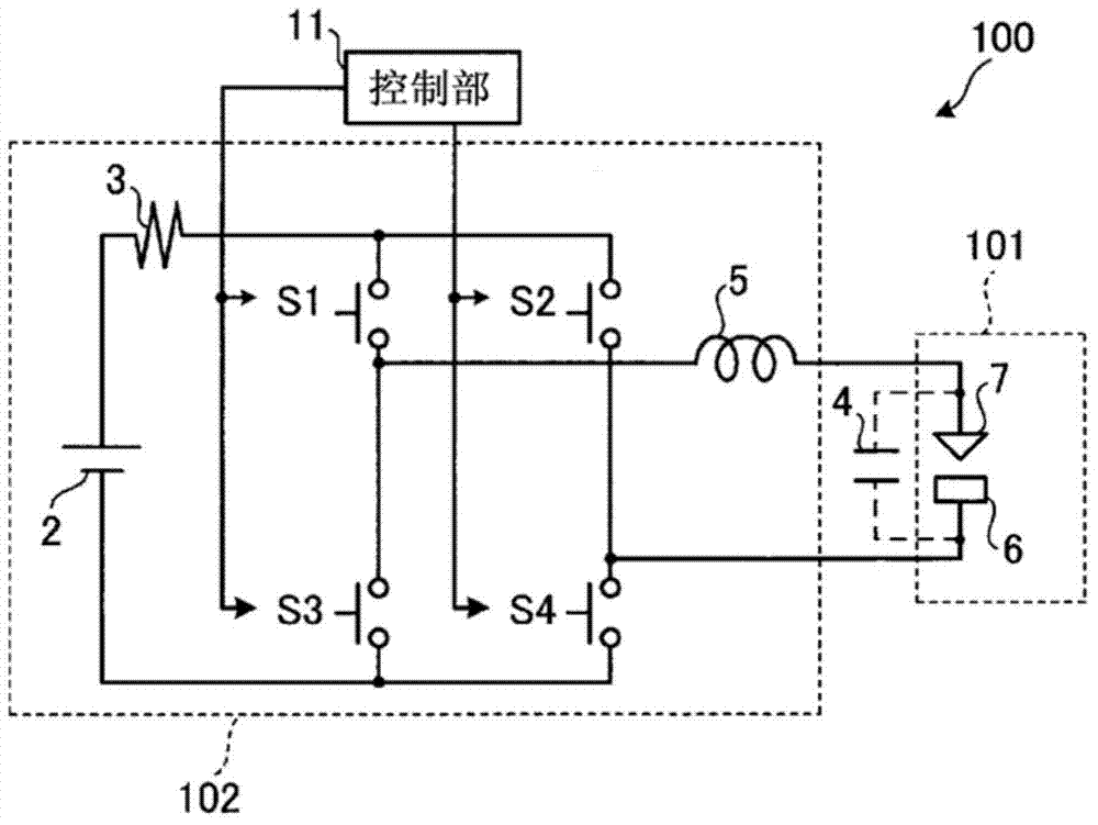
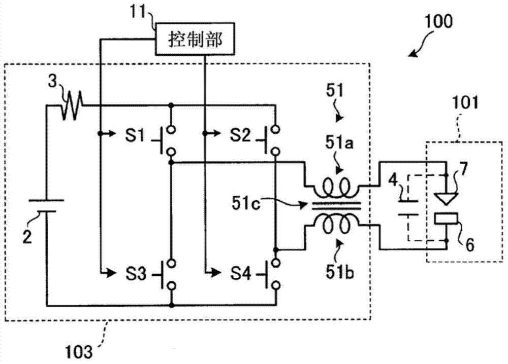
[0037] use figure 1 , figure 2 The electrical discharge machining device 100 according to Embodiment 1 will be described. figure 1 It is a diagram showing a configuration example of the electrical discharge machining device 100 . figure 2 It is a diagram showing another configuration example of the electrical discharge machining device 100 .

[0038] For example, if figure 1 As shown, the electrical discharge machining device 100 includes an inter-electrode gap 101 , a power supply unit 102 , and a control unit 11 .

[0039] Inter-electrode gap 101 is formed by electrode 7 and workpiece 6 . The electrode 7 and the workpiece 6 face each other across a machining gap. The workpiece 6 is grounded to the ground potential, for example. The capacitance 4 existing between the electrode 7 and the workpiece 6 can be inserted arbitrarily, and a parasitic capacitance existing in a mechanical structure such as a cable can also be used.

[0040] The capacitance 4 provided in the in...

Embodiment approach 2

[0079] Next, use Figure 5 , Image 6 An electric discharge machining device 100i according to Embodiment 2 will be described. Figure 5 It is a figure which shows the structural example of 100i of electrical discharge machining apparatuses. Image 6 It is a figure which shows another structural example of the electrical discharge machining apparatus 100i. Hereinafter, description will focus on parts different from Embodiment 1. FIG.

[0080] In Embodiment 1, the on-pulse time width ΔTon and the off-time width ΔToff in the switching mode (oscillating signal) are, for example, values ​​obtained through experiments in advance. On the other hand, in the second embodiment, the on-pulse time width ΔTon and the off-time width ΔToff in the switching mode (oscillating signal) are dynamically adjusted according to the state of the inter-electrode space 101 .

[0081] For example, if Figure 5 shown, with figure 1 Compared with the shown electric discharge machining device 100 , t...

Embodiment approach 3

[0101] Next, use Figure 8 and Figure 9 An electrical discharge machining device 100j according to Embodiment 3 will be described. Figure 8 It is a figure which shows the structural example of 100 j of electrical discharge machining apparatuses. Figure 9 It is a figure which shows another structural example of the electrical discharge machining apparatus 100j. Hereinafter, description will focus on portions different from Embodiment 2. FIG.

[0102] In Embodiment 2, the on-pulse time width and the off-time width in the switching mode are adjusted so that the input energy to the inter-electrode space 101 is substantially constant based on the state of the inter-electrode space 101 detected by the detection unit 10i. On the other hand, in Embodiment 3, according to the state of the inter-electrode 101 detected by the detection part 10i, the on-pulse time width and off-time width in switching mode are adjusted so that the short circuit of the inter-electrode 101 can be elim...


PUM


Abstract

The present invention is capable of improving machining accuracy and machining efficiency by providing a regular rest time during a cycle in which machining is considered to become unstable during machining performed by the self-oscillation of a capacitor discharge in which the inter-electrode capacitance of a capacitor is used. This electrical discharge machining apparatus is provided with: a power source; an inter-electrode space formed by an electrode and the workpiece; a current-limiting resistor connected between the power source and the inter-electrode space; a switching element for turning on and off the application of voltage from the power source to the inter-electrode space; an inductance element connected serially between the switching element and the inter-electrode space; and a control unit for controlling the switching element, the control unit causing the switching element to turn on and off according to a switching pattern having an on-pulse duration (ΔT on) such that during the on-pulse time the voltage of the inter-electrode space can reach the voltage of the power source, and a rest duration (ΔT off) that ranges from the duration (ΔT ic) of the discharge current flowing during discharge of the capacitor, to less than the self-oscillation cycle (ΔT so).

Description

technical field [0001] The invention relates to a discharge machining device. Background technique [0002] An electrical discharge machining device is a device that processes a workpiece by generating an arc discharge between a machining electrode and the workpiece. An electric discharge machining device requires a power source (machining power source) for generating arc discharge. There are currently various configurations of the machining power source. [0003] Among them, a capacitive discharge method using capacitance between electrodes existing in parallel between the electrodes is known. The basic circuit is composed of power supply, current limiting resistor, and capacitance between electrodes. When the capacitive element is connected in parallel between the electrodes, the capacitance between the electrodes is synthesized by the mechanical parasitic capacitance between the electrode and the workpiece and the capacitance of the capacitive element. When the capacit...

Claims


Application Information

Patent Timeline
IPC IPC(8): B23H1/02
CPCB23H1/02B23H2300/20B23H1/024
Inventor 金利映桥本隆高田智昭中川孝幸佐佐木祐飞
Owner MITSUBISHI ELECTRIC CORP
Why Eureka
Try Eureka