
Discharge mechanism and discharge method of energy-level molecular material cell tearing equipment

A technology of molecular material and discharging mechanism, which is applied in the chemical/physical/physical chemical process of applying energy, microsphere preparation, microcapsule preparation, etc. It can solve the problem of small-scale production, high equipment demand, and temperature difference crushing cost. higher question

Inactive Publication Date: 2017-05-10
广东如动纳米科技有限公司
View PDF4 Cites 0 Cited by
  • Summary
  • Abstract
  • Description
  • Claims
  • Application Information

AI Technical Summary

Problems solved by technology

The existing problems are: group or filamentous fungal molecular cells that are easy to cause blockage, small Gram-positive heads and some sub-molecular cells, which are hard in texture and easy to damage the homogenate valve, and are not suitable for this method.
The problem is: there are many operating parameters, generally estimated by experience and the liquid loss between the beads is about 30%
Existing problems: the construction of a low-temperature environment requires high equipment requirements, and the cost of using temperature difference crushing is relatively high
The problem is; easy to cause product inhibition, which may be an important factor leading to low release rate of intracellular substances
Existing problems: the amount of synthesis is not large, only a small amount of production can be produced, the hourly output is only about 100 grams, the cost is expensive and many structures and properties of the material are changed, and the change of the material phase limits its application field

Method used

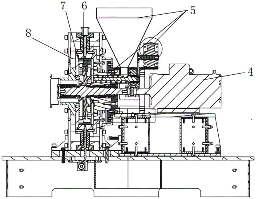
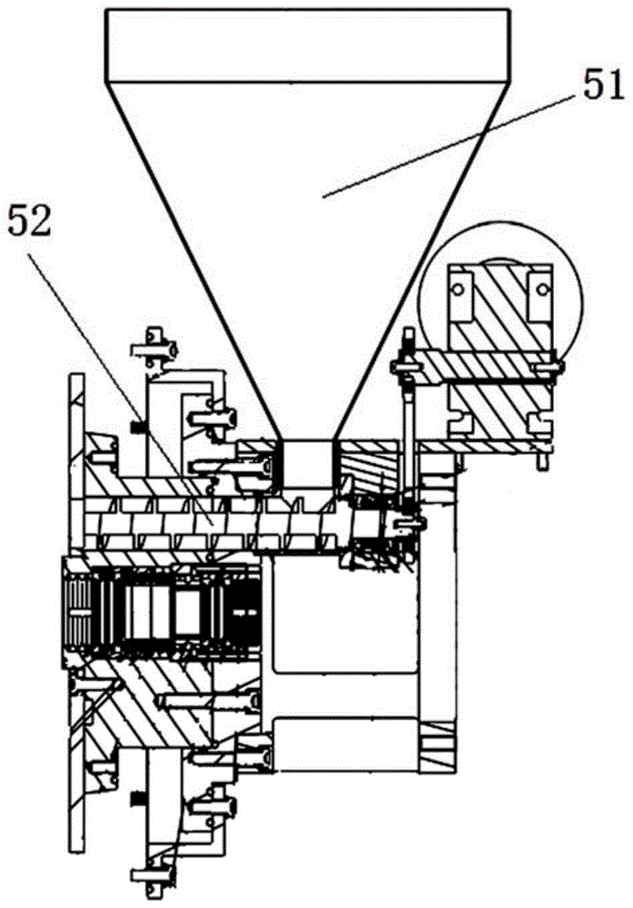

Image

  • Discharge mechanism and discharge method of energy-level molecular material cell tearing equipment
  • Discharge mechanism and discharge method of energy-level molecular material cell tearing equipment
  • Discharge mechanism and discharge method of energy-level molecular material cell tearing equipment

Examples


Embodiment Construction

[0039] In order to facilitate those skilled in the art to better understand the essence of the present invention, the specific implementation manners of the present invention will be described in detail below in conjunction with the accompanying drawings.

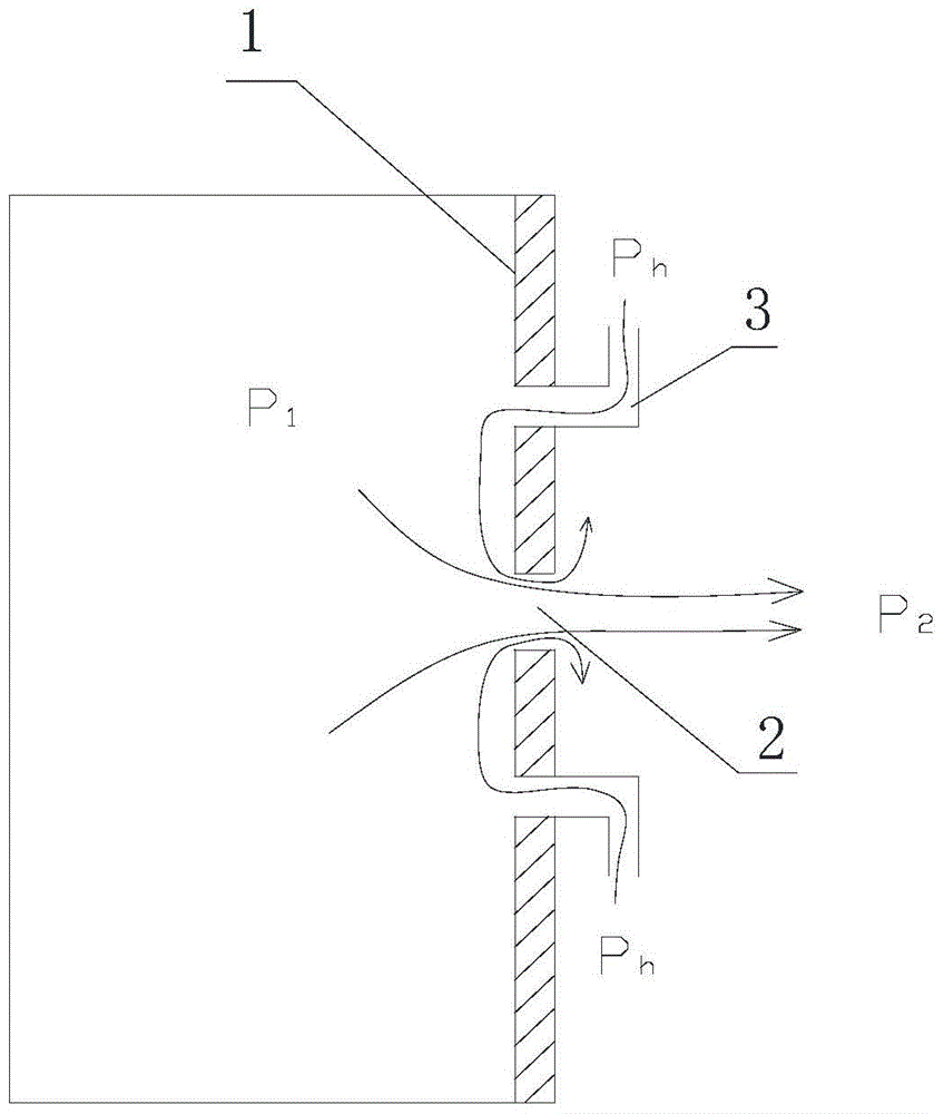
[0040] Such as figure 1 As shown, a discharge mechanism of an energy-level molecular material cell tearing device includes: a baffle 1, at least one material outlet 2 passing through the baffle 1, and at least two negative feedbacks arranged around the material outlet 2 Pressure regulator port 3.

[0041] The specific working principle is: set the baffle plate 1 on the energy field cavity of the cell tearing equipment, and act as one side of the energy field cavity. In the energy field cavity, the centrifugal force and centripetal force are used to make the material with large mass thrown by the centrifugal force. to the edge of the energy field cavity; under the action of the pressure difference, the centripetal force mak...


PUM


Abstract

The invention discloses a discharging mechanism of energy-level molecular material cell tearing equipment. The discharging mechanism is characterized by comprising a baffle, at least one material guide outlet penetrating through the baffle, and at least two negative feedback pressure adjusting holes formed in the periphery of the material guide outlet. During actual working, the baffle is arranged on an energy field cavity of the cell tearing equipment and serves as a side surface of the energy field cavity, and materials with large mass are thrown to the edge of the energy field cavity by centrifugal force under the action of centrifugal and centripetal forces in the energy field cavity; materials with small mass are collected to the center of the energy field cavity by the centripetal force under the action of a pressure difference, so that the materials are guided out and collected by the material guide outlet and screenless separation of the materials is realized. Particularly, when the materials are guided out, feedback air pressure is injected into the negative feedback pressure adjusting holes at the same time to effectively guarantee that the materials are guided out stably and uniformly.

Description

technical field [0001] The invention relates to the field of nanomaterial preparation, in particular to a discharge mechanism and a discharge method of an energy-level molecular material cell tearing device. Background technique [0002] At present, the preparation methods and equipment of nanomaterials mainly include the following types: [0003] 1) High-pressure homogenization method: the equipment is a high-pressure homogenizer, which is composed of a high-pressure pump and a homogenization room. Both the British ADV company and the American Microfluidics company have products for sale. Its crushing mechanism: Molecular cells have experienced scissors caused by high speed, collisions and changes from high pressure to normal pressure in a series of processes, resulting in the fragmentation of molecular cells. The existing problems are: group-shaped or filamentous fungal molecular cells that are more likely to cause blockage, smaller Gram-positive heads and some sub-molecu...

Claims


Application Information

Patent Timeline
Patent Type & Authority Patents(China)
IPC IPC(8): B01J19/10B01J13/02
Inventor 杨华林海卫
Owner 广东如动纳米科技有限公司
Learn More