Inductive microcurrent cutter breaking detection circuit

A detection circuit and knife breaking technology, which is applied in the detection field, can solve the problems of high error rate and low detection sensitivity, and achieve the effects of high detection sensitivity, ensuring production quality and production efficiency

Active Publication Date: 2015-07-22
遂川天马数控有限公司
View PDF6 Cites 5 Cited by
  • Summary
  • Abstract
  • Description
  • Claims
  • Application Information

AI Technical Summary

Problems solved by technology

However, some existing detection methods for broken knives often have problems such as low detection sensitivity and high error rate.

Method used


Image

  • Inductive microcurrent cutter breaking detection circuit
  • Inductive microcurrent cutter breaking detection circuit
  • Inductive microcurrent cutter breaking detection circuit

Examples


Embodiment Construction

[0017] In order to facilitate the understanding of those skilled in the art, the present invention will be further described in detail below with reference to the drawings and embodiments.

[0018] The circuit of the present invention includes an excitation signal generating circuit, an excitation signal conversion circuit, a signal transmitting circuit, a signal sensing circuit and a signal processing circuit sequentially connected by signals. In addition, it also includes a power supply module for supplying power to each functional module.

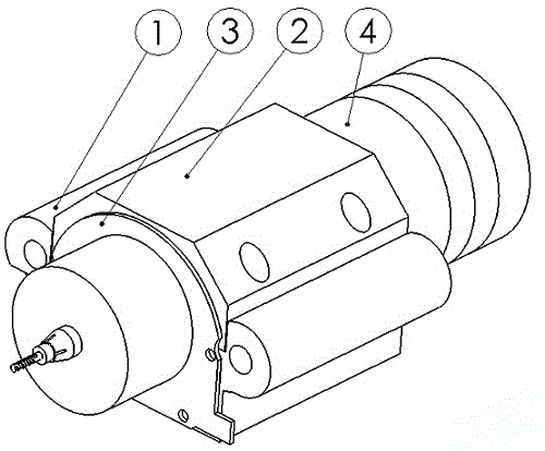
[0019] Among them, the signal transmission circuit and the signal induction circuit adopt magnetic ring coils, and the two sets of coils are sleeved outside the main shaft and fixed on the main shaft base with screws. Such as figure 1 As shown, two groups of coils, one large and one small for transmitting and sensing, form a magnetic ring coil 3, which is set outside the main shaft 4 and fixed on the main shaft seat 1 with screws. The m...


PUM


Abstract

The invention discloses an inductive microcurrent cutter breaking detection circuit. The circuit comprises an excitation signal generation circuit, an excitation signal conversion circuit, a signal transmitting circuit, a signal induction circuit and a signal processing circuit, all of which are in sequential signal connection. The inductive microcurrent cutter breaking detection circuit further comprises a power module supplying power to all function modules. The signal transmitting circuit and the signal induction circuit adopt magnetic loop coils. The coils are arranged outside a spindle in a sleeving mode to be fixed to a spindle seat through screws. The excitation signal generation circuit outputs an oscillation signal at the fixed frequency to a transmitting coil. When a cutter drills a workpiece, an induction coil will generate induction current. When equipment normally runs, a detection loop will output a detection signal every time a hole is drilled, and meanwhile a PC compares a current position with an average value of the current position in real time, so that whether a drill bit is broken or not is judged. Compared with the prior art, the inductive microcurrent cutter breaking detection circuit can detect the condition of the machine tool cutter in real time, the cutter breakage phenomenon is found in time, the detection sensitivity is high, and the production quality and efficiency can be effectively ensured.

Description

technical field [0001] The invention relates to the field of detection, in particular to a circuit for detection of tool interruption in drilling tool work engineering. Background technique [0002] At present, when CNC drilling machines for printed circuit boards process micro-holes, the requirements for drilling speed and precision are getting higher and higher. The thinner the drill is, the easier it is to break. In this case, it is extremely important to be able to detect the status of the broken knife accurately in real time. However, some existing detection methods for broken knives often have problems such as low detection sensitivity and high error rate. Contents of the invention [0003] The technical problem to be solved by the invention is to provide a high-sensitivity, stable and reliable inductive micro-current knife breaking detection circuit. [0004] The technical solution provided by the present invention is: an inductive micro-current knife breaking...

Claims


Application Information

Patent Timeline
Patent Type & Authority Applications(China)
IPC IPC(8): B26D7/00G01V3/12B26F1/16
Inventor 周启发
Owner 遂川天马数控有限公司
Why Eureka
Try Eureka