Loose stock dyeing device with rotatable fiber cage

A dyeing device and fiber cage technology, which is applied in the direction of textile material equipment configuration, textile material contact export textile material treatment, etc., can solve the problems of affecting the recycling of dyestuffs, damage to fiber cages and dye vats, and increased maintenance costs, etc., to achieve Not easy to agglomerate, reduce equipment maintenance cost, and reduce wear and tear

Inactive Publication Date: 2015-07-22
湖州市菱湖东方丝织厂
View PDF5 Cites 6 Cited by
  • Summary
  • Abstract
  • Description
  • Claims
  • Application Information

AI Technical Summary

Problems solved by technology

In the traditional loose fiber dyeing device, when the fiber cage is hoisted into the dyeing vat, the bottom of the fiber cage directly collides with the dyeing vat hard, causing damage to the fiber cage and the dyeing vat
At the same time, the existing bulk fiber dyeing device does not have a stirring device when adding dye, the dye is easy to agglomerate, which affects the subsequent dye recycling, and the fiber cage generally does not move or rotate after being put in, which makes the dyeing process only Exhaust dyeing is carried out by spraying color through the injection hole, resulting in uneven dyeing and low dyeing efficiency. In addition, the recycling of dyes with circulating pumps requires decontamination of dyes, otherwise the circulating pumps will be blocked, which requires regular cleaning and maintenance, increasing maintenance. cost, it is necessary to improve

Method used


Image

  • Loose stock dyeing device with rotatable fiber cage
  • Loose stock dyeing device with rotatable fiber cage
  • Loose stock dyeing device with rotatable fiber cage

Examples


Embodiment Construction

[0024] The specific implementation manners of the present invention will be further described in detail below in conjunction with the accompanying drawings and embodiments. The following examples are used to illustrate the present invention, but are not intended to limit the scope of the present invention.

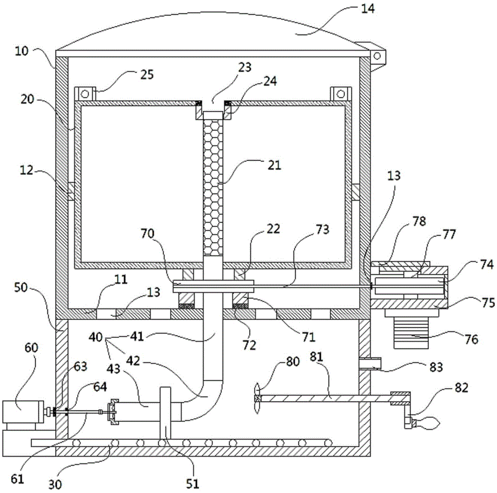
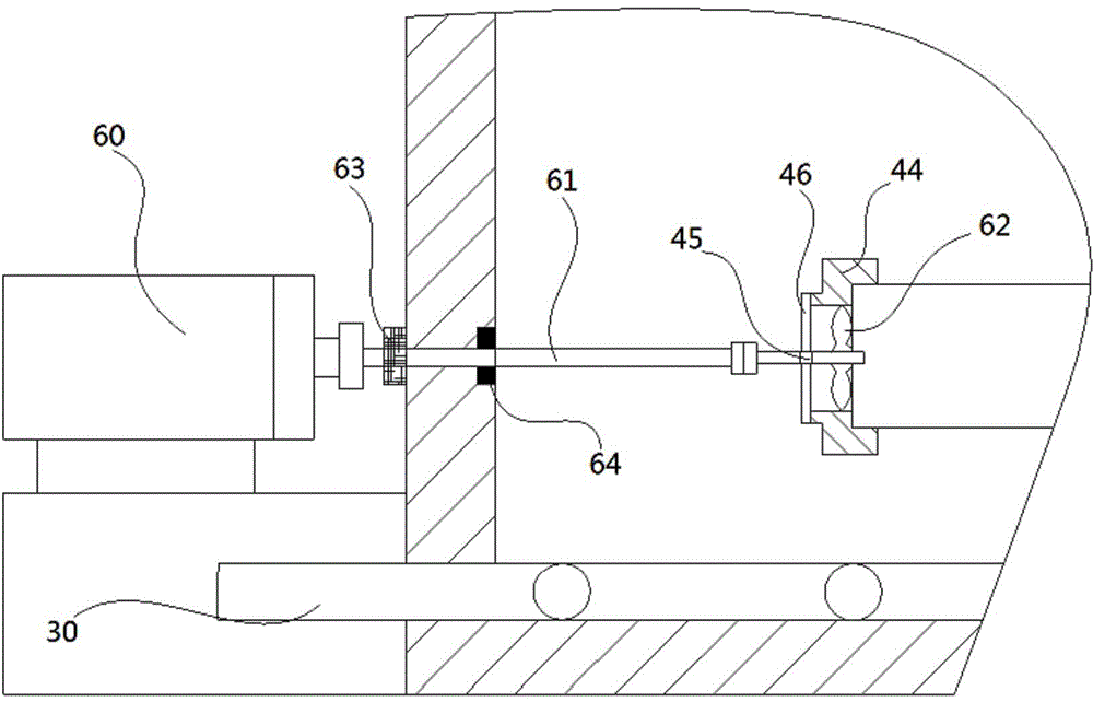
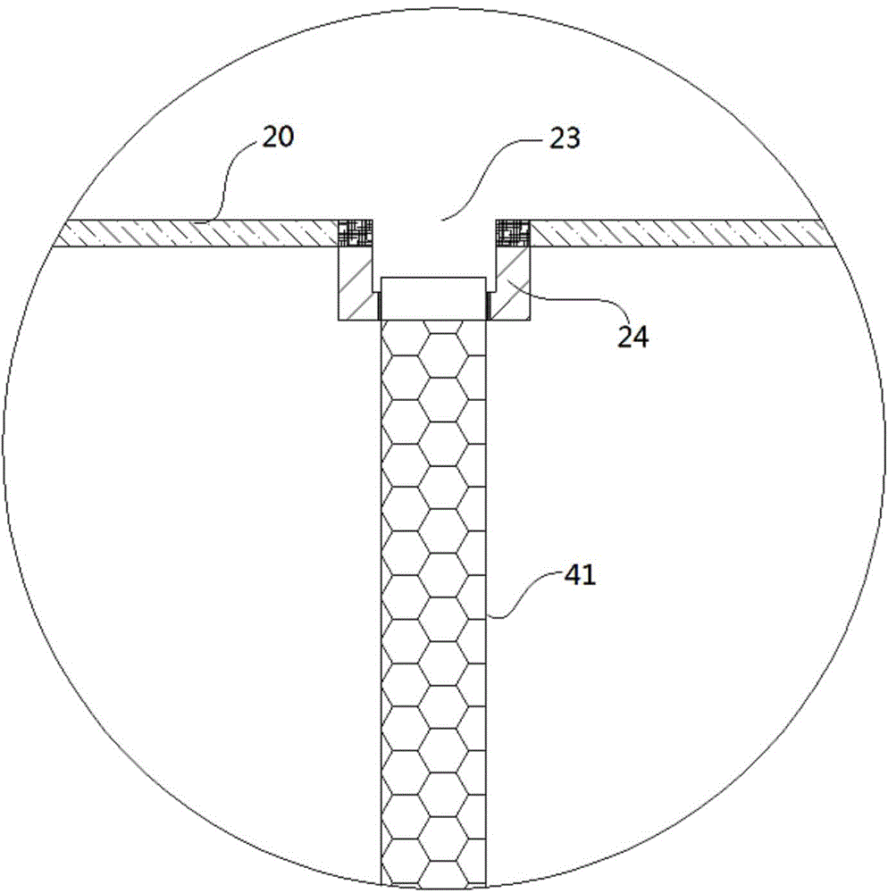
[0025] see Figure 1 to Figure 4 , the loose fiber dyeing device with rotatable fiber cage of the present invention comprises dyeing vat 10, fiber cage 20, heating coil 30 and center spray pipe 40, the bottom of described dyeing vat 40 is fixed with dye tank 50, and the dyestuff A heating coil 30 is fixed on the bottom of the tank 50, and one end of the heating coil 30 extends out of the dye tank 50 and communicates with the steam source; the outer wall of the dye tank 50 is fixed with a driving motor 60, and the output shaft of the driving motor 60 is passed through a shaft coupling. The device is connected with an intermediate rotating shaft 61, the intermediate rotatin...


PUM


Abstract

The invention discloses a loose stock dyeing device with a rotatable fiber cage. The loose stock dyeing device comprises a dyeing vat, the fiber cage, a heating coil pipe and a central spraying pipe, a dye tank is fixed to the bottom of the dyeing vat, a rotary wheel is arranged between the fiber cage and a bottom plate of the dyeing vat, and the rotary wheel is connected with a driving wheel through a driving belt. A mounting hole is formed in the upper end face of the rotary wheel, a mounting shaft corresponding to the mounting hole is arranged at the bottom end of the fiber cage, a locating hole is formed in the top of the fiber cage, locating blocks are arranged on the two sides of the locating hole, the upper side of the central spraying pipe is clamped by the locating blocks, and dye through holes communicated with the dye tank are evenly formed in the bottom plate of the dyeing vat. A stirring impeller is arranged in the dye tank, the stirring impeller is arranged on a lead screw, the end of the part, stretching out of the dye tank, of the lead screw is in pivot joint with a stirring handle, and a dye adding opening is formed in the position, on one side of the lead screw, of the side wall of the dye tank. When the fiber cage is hoisted down into the dyeing vat, the fiber cage does not rigidly collide with the dyeing vat, dye is not likely to be caked when added, the fiber cage rotates, and therefore dyeing is more even.

Description

Technical field: [0001] The invention relates to the technical field of textile printing and dyeing equipment, in particular to a loose fiber dyeing device with a rotatable fiber cage. Background technique: [0002] In the field of textile printing and dyeing, in order to obtain a certain effect on cotton yarn, loose fiber dyeing can be used. In the traditional loose fiber dyeing device, when the fiber cage is hoisted into the dyeing vat, the bottom of the fiber cage directly collides with the dyeing vat hard, causing damage to the fiber cage and the dyeing vat. At the same time, the existing bulk fiber dyeing device does not have a stirring device when adding dye, the dye is easy to agglomerate, which affects the subsequent dye recycling, and the fiber cage generally does not move or rotate after being put in, which makes the dyeing process only Exhaust dyeing is carried out by spraying color through the injection hole, resulting in uneven dyeing and low dyeing efficiency....

Claims


Application Information

Patent Timeline
Patent Type & Authority Applications(China)
IPC IPC(8): D06B1/08D06B23/20
Inventor 顾明琴
Owner 湖州市菱湖东方丝织厂
Why Eureka
Try Eureka