
Processing equipment and method for continuous fiber tows

A technology of fiber tow and processing equipment, applied in the field of fiber tow, can solve the problems of reduced expansion effect, inability to obtain high-quality products, and incomplete presentation.

Inactive Publication Date: 2015-07-22
FORMOSA TAFFETA CO LTD
View PDF15 Cites 25 Cited by
  • Summary
  • Abstract
  • Description
  • Claims
  • Application Information

AI Technical Summary

Problems solved by technology

Because it is mainly through tension and friction, if the tension of the fiber tow is unstable when the fiber is released, the width of the tow after unfolding will be unstable.
[0014] 3. JP Patent No. Hei 3-31823: Carbon fiber multi-filament bundles pass through an expanding device with multiple roller rods, supplemented by vibration in the axial direction, and the rollers are arranged in a dislocation manner, and the fiber bundles are arranged at 30 degrees to The disadvantage of the 90-degree entry and exit angle is that the tension of the fiber tow is unstable when it is discharged, which will make the width of the tow unrolled unstable and easily cause a large number of fiber breaks
[0015] 4. JP Patent No. Hei 1-282362: Ultrasonic waves are used to vibrate in the direction of the fiber tow, supplemented by high-pressure gas to increase the width of the tow and reduce the distribution density of single fibers. The disadvantage is that the fiber tow moves forward Tension tends to reduce the expansion effect, so it cannot be used to make larger expansion
[0016] 5. JP Patent No. Zhao 57-77342: In the vertical direction of the fiber tow traveling direction, the fluid movement of gas or liquid generates fiber tow dispersion force, which promotes the increase of the width of the tow and reduces the distribution density of single fibers , its disadvantage is that the expansion effect is likely to be reduced due to the forward tension of the fiber tow, so it cannot be used to make larger expansions, and the width is difficult to control stably
[0017] 6. JP Patent No. Zhao 52-151362: In the vertical direction of the fiber tow traveling direction, the fiber tow is dispersed by the fluid force of ejecting gas or liquid, so as to increase the width of the tow and reduce the distribution density of single fibers. Its disadvantage is that the forward tension of the fiber tow tends to reduce the expansion effect, so it cannot be used to make larger expansions, and the width is difficult to control stably, and the fibers are easy to be blown.
Among them, the tension friction dispersion method of the round rod has a good dispersion effect, but due to the friction between the fiber and the surface of the round rod, a large number of fibers are broken, the tension when the fiber tow is pulled out cannot be stabilized, and the width of the dispersed fiber tow varies. It is impossible to obtain high-quality products with uniform width of single fiber tow, and can only be used for prepreg products with traditional thermosetting high fiber distribution density; fluid dispersion method or vibration dispersion method is used in known patented technologies, most of which are used as tension The auxiliary method of the dispersion method cannot be used as the main method of the low fiber distribution density process. If you want to obtain a product with a uniform width of the dispersed fiber tow, you must have other auxiliary devices to limit or adjust the width.
For the production technology of single fiber tow with low and uniform fiber distribution, most of the known technologies have not completely proposed a feasible method, so the industry is still looking for a method that can be applied to thermoplastic unidirectional prepreg production technology

Method used


Image

  • Processing equipment and method for continuous fiber tows
  • Processing equipment and method for continuous fiber tows
  • Processing equipment and method for continuous fiber tows

Examples


example

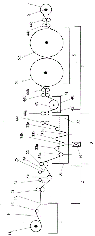
[0099] For the specific implementation of the processing equipment of the continuous fiber tow of the present invention, please refer to figure 1 As shown, the filament supply unit 1 fixes the fiber tow F to a fixing device 11, and the fixing device 11 has a fixed tension controller, which can keep the fiber tow F at a fixed and stable tension when it is pulled out. Then, when the fiber tow F is output from the yarn supply unit 1 through the guide roller 12 and the guide hole 13, the fiber tow F can be prevented from being pulled out unstable or the state of unstable tension can be avoided.

[0100] In order to ensure stable tension and fixed fiber tow F width when the fiber tow F enters or leaves the desizing unit 2, a pair of guide rollers are respectively arranged at the inlet and outlet of the desizing unit 2 21 / 22, the guide wire roller group 21 / 22 is respectively arranged at the feed inlet and the discharge outlet of the desizing unit 2, and the feed inlet is to accept t...


PUM

PropertyMeasurementUnit
Sizeaaaaaaaaaa
Sizeaaaaaaaaaa
Sizeaaaaaaaaaa

Abstract

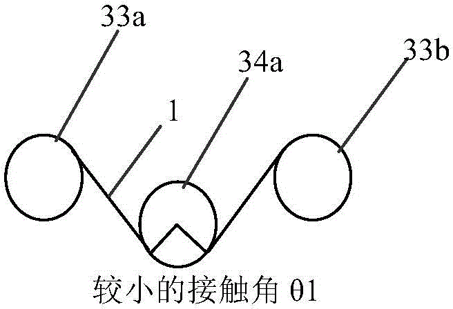
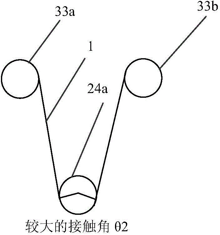
The invention relates to processing equipment and method for continuous fiber tows. The processing equipment comprises a desizing unit, an unfolding and dispersing unit and a sizing unit, wherein the desizing unit uses a fluid washing mode to enable fiber tows to desize, the unfolding and dispersing unit comprises round bars, tension braking rollers and a tension brake which are alternatively arranged, the round bars and the tension braking rollers are used for controlling the contact angles between the fiber tows and the adjacent round bars, the tension brake is connected to each tension braking roller and then used for regulating the tension generated when the tension braking rollers rotate, and the sizing unit is used for conducting re-sizing and drying on the fiber tows. The method for the continuous fiber tows is achieved through the above equipment, the fiber tows after being processed have lowered and uniform fiber distribution density and stable and consistent fiber tow widths, and therefore the fiber tows together with heat plastic plastics can directly be made into heat plastic composite materials or various types of composite material products.

Description

technical field [0001] This application relates to a method for processing continuous fiber tows, in particular to a method capable of reducing fiber distribution density, making fiber distribution density uniform, and obtaining fiber tows with stable and consistent width of fiber tows. [0002] The present application also relates to a continuous fiber tow processing equipment, which can be used in the above processing method, so as to achieve better results. Background technique [0003] The so-called fiber reinforced plastic composite material (fiber reinforced plastic composite) of the present invention is to take resin as base material, and fiber is used as the composite material of reinforcing material, commonly used fiber reinforced plastic composite material includes glass fiber, carbon fiber, boron fiber and Composite materials such as Kevlar fiber, for example, glass fiber reinforced plastic (FRP) bathtub is the most common application of glass fiber composite mate...

Claims


Application Information

Patent Timeline
IPC IPC(8): D06B21/00D06B23/04D06B23/06D06B3/04
Inventor 蔡天玄苏稳生陈文山连金星吴太镒
Owner FORMOSA TAFFETA CO LTD
Learn More