Supercharge Your Innovation With Domain-Expert AI Agents!

Laser power meter

A laser power meter and laser technology, applied in the field of laser power meters, can solve the problems of narrow spectral coverage, narrow power range, and long response time of power meters, and achieve wide spectral coverage, short response time, and measurable power range wide effect

Inactive Publication Date: 2015-07-22
BEIJING INST OF OPTO-ELECTRONIC TECH
View PDF5 Cites 6 Cited by
  • Summary
  • Abstract
  • Description
  • Claims
  • Application Information

AI Technical Summary

Problems solved by technology

[0004] The advantage of the photoelectric laser power meter is that the response time is fast, but its spectral coverage is narrow, and the measurable power range is also narrow
The calorimetric laser power meter has the advantages of wide spectral coverage and large power measurable range. Therefore, for the measurement of medium-power and high-power lasers, as well as for the laser power For comparative measurements, a calorimetric laser power meter is usually used, but the response time of this power meter is long
The above two laser power meters have their own shortcomings, and it is difficult to meet the requirements of various lasers in the measurement process

Method used


Image

  • Laser power meter
  • Laser power meter

Examples


Embodiment 1

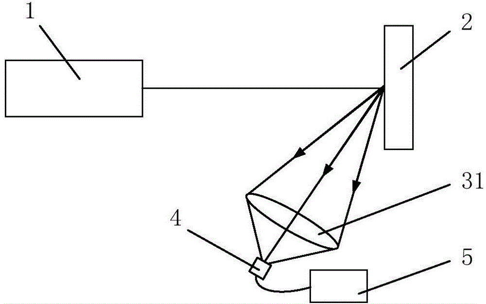
[0027] In view of the fact that the two commonly used laser power meters in the prior art each have some shortcomings, and cannot meet the needs of individual or combined measurement of multiple lasers during the measurement process, this embodiment provides a laser power meter that has spectral coverage The advantages of wide range and wide measurable power range also have the advantage of short response time.

[0028] The laser power meter provided in this embodiment includes: a laser converter, an infrared receiver, an infrared detector, and a power tester. Among them, the laser converter is used to absorb the incident laser light and convert the incident laser light into infrared rays to emit outward. The infrared receiver is used to receive the infrared rays emitted by the laser converter and converge the infrared rays. The infrared detector is used to receive the converged infrared rays and convert the energy of the converged infrared rays into electrical signals. The ...

Embodiment 2

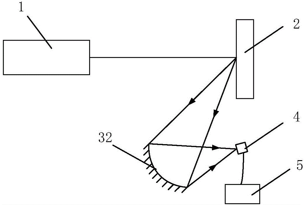
[0048] The first embodiment above provides a laser power meter composed of a transmissive infrared receiver 31 . The difference from the first embodiment is that the infrared receiver in the laser power meter provided by this embodiment is reflective. figure 2 A schematic structural diagram of a laser power meter provided in Embodiment 2 of the present invention. Such as figure 2 As shown, the laser power meter detects the laser light emitted by the laser 1 to be tested, and the laser power meter may include: a laser converter 2 , a reflective infrared receiver 32 , an infrared detector 4 and a power tester 5 .

[0049] Wherein, the laser converter 2 can also be called a test target, as the name implies, it is used to receive the incident laser light emitted by the laser 1 . The photosensitive surface of the laser converter 2 receives the incident laser light, which causes the temperature of the part of the laser converter 2 irradiated by the incident laser light to rise, a...


PUM


Abstract

The invention provides a laser power meter. The laser power meter comprises a laser converter, an infrared receiver, an infrared detector and a power tester, wherein the laser converter is used for absorbing incidence laser, and converting the incidence laser into infrared rays to be emitted outwards; the infrared receiver is used for receiving the infrared rays and converging the infrared rays; the infrared detector is used for receiving the converged infrared rays and converting the converged infrared rays into an electric signal; the power tester is connected with the infrared detector and is used for receiving the electric signal, and calculating to obtain a power value of the incidence laser according to the electric signal. The laser power meter provided by the invention has the advantages of wide spectrum covering range and wide measurable power range, and also has the advantage of short responding time.

Description

technical field [0001] The invention relates to laser power detection technology, in particular to a laser power meter. Background technique [0002] With the development of laser technology, lasers are widely used in communication, medical, industrial manufacturing and other fields. In the process of laser development, production and application, it is an essential step to measure and calibrate the power of the laser. [0003] A laser power meter is a device for measuring laser power. According to different measurement principles, laser power meters mainly include two types, photoelectric laser power meters and calorimetric laser power meters. Among them, the photoelectric laser power meter uses the photoelectric effect of semiconductors to realize power measurement. When the laser is irradiated on the detection photosensitive surface of the photoelectric laser power meter, a photocurrent will be formed in the circuit where the PN junction is located. The higher the power ...

Claims


Application Information

Patent Timeline
Patent Type & Authority Applications(China)
IPC IPC(8): G01J1/56G01J5/10
Inventor 王涛张玉莹陆耀东张丽雯孙岩张萍宋金鹏
Owner BEIJING INST OF OPTO-ELECTRONIC TECH
Features
  • R&D
  • Intellectual Property
  • Life Sciences
  • Materials
  • Tech Scout
  • Unparalleled Data Quality
  • Higher Quality Content
  • 60% Fewer Hallucinations
Learn More