Digital formed beam design method of digital array radar

A digital array radar and shaped beam technology, which is applied in radio wave measurement systems and instruments, can solve the problem of high sidelobe level in the shaped beam pattern, achieve good performance, low algorithm complexity, and strong anti-interference performance Effect

Active Publication Date: 2015-07-22
NANJING UNIV OF SCI & TECH
View PDF1 Cites 14 Cited by
  • Summary
  • Abstract
  • Description
  • Claims
  • Application Information

AI Technical Summary

Problems solved by technology

In the article "Conformal array synthesis including mutual coupling" published by Electron.Lett (Electron.Lett., 1999, 35, (8), pp.625–627), the 16-element The cosecant square beam synthesis is achieved by using the ortho

Method used


Image

  • Digital formed beam design method of digital array radar
  • Digital formed beam design method of digital array radar
  • Digital formed beam design method of digital array radar

Examples


Embodiment 1

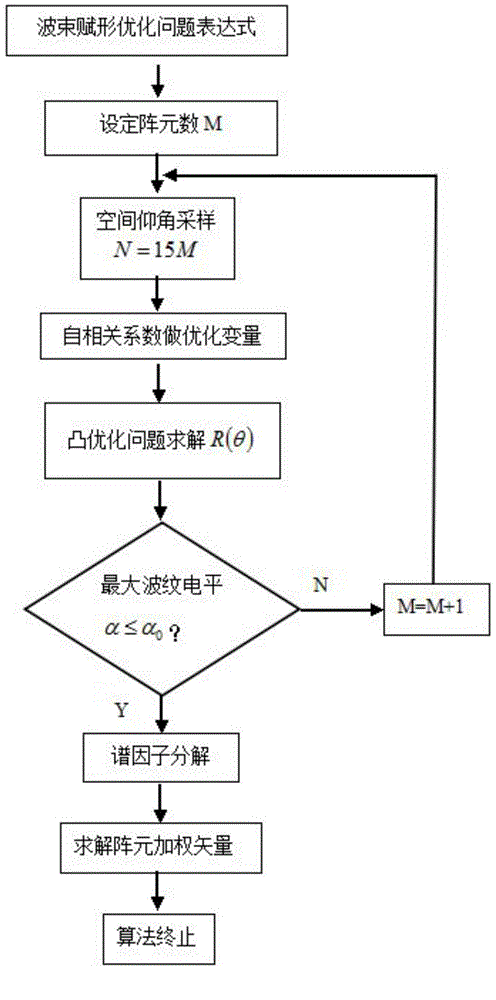
[0040] The present invention uses the following parameters to verify.

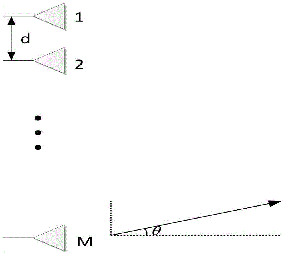
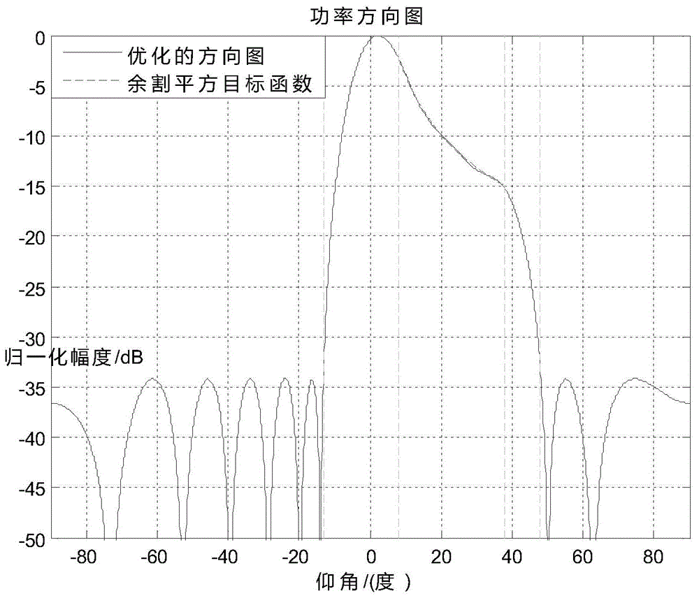
[0041]M array elements are arranged vertically and evenly, the spacing between antenna elements is d=λ / 2, the shaping area is [8°, 38°], and the objective function of shaping is D(θ)=cscθ(8°≤θ≤38 °), the low side lobe area is [-90°,-12°]∪[48°,90°], the side lobe attenuation level is set to -40dB, and the required value of the maximum ripple level is α 0 = 0.03dB.

[0042] Transform the cosecant squared beam design problem into the following optimization model

[0043] minimize α 2

[0044] subject to 1 / α 2 ≤R(θ) / |D(θ)| 2 ≤α 2 ,θ∈[θ p1 ,θ p2 ]

[0045] R(θ)≤δ 2 ,θ∈[-90°,θ s1 ]∪[θ s2 ,90°]

[0046] R(θ)≥0 for allθ∈[-90°,90°]

[0047] Among them, δ=-40dB.

[0048] Sampling the elevation angle 8°≤θ≤38° to obtain a set of discrete elevation angle values: -90°≤θ 1 ≤θ 2 ≤...≤θ N ≤90°. Here, N=15M is taken, M is the number of array elements, and the initial value M=12 is se...


PUM


Abstract

The invention provides a digital formed beam design method of a digital array radar. The digital formed beam design method includes arranging M array elements vertically and evenly into an M array element linear array; taking an autocorrelation coefficient of an array weighting vector of the array element linear array as an optimal variable, and creating and solving a convex optimization model to acquire a globally optimal solution of an array pattern function amplitude square and a maximum ripple level of a forming region; comparing the maximum ripple level of the forming region with a required value of the maximum ripple level to judge whether an optimization result meets design requirements or not; if yes, performing spectral decomposition on the array pattern function amplitude square to acquire an optimal solution of the array weighting vector, and outputting the optimal solution as an optimal beam forming vector. The digital formed beam design method has the advantages that when the number of the array elements is small, good performance of an optimized pattern minor lobe level, the optimized maximum ripple level of the forming region and the like can be still kept, and algorithm complexity is low.

Description

technical field [0001] The invention relates to a digital beam forming technology in a digital array radar system, in particular to a digital beam forming method for a digital array radar. Background technique [0002] Digital array radar (DAR) is a fully digital array scanning radar that adopts digital beamforming technology for both receiving and transmitting beams. Compared with traditional phased array radar, digital array radar has many advantages: (1) It is easy to realize ultra-low (2) The signal processing method is flexible; (3) Direct frequency synthesis (DDS) technology can be used; (4) No radio frequency or microwave phase shifter is required; (5) The whole machine of the radar has low power consumption and high reliability. high. [0003] Conventional shaped beam design usually uses some analysis techniques, such as Taylor series and Chebyshev method, but it will produce large ripples in the shaped area, so in order to get better shaping effect, the stochastic ...

Claims


Application Information

Patent Timeline
IPC IPC(8): G01S7/02
CPCG01S7/02G01S7/2813
Inventor 秦夷朱唯唯张家庆王芮谢仁宏芮义斌郭山红李鹏
Owner NANJING UNIV OF SCI & TECH
Why Eureka
Try Eureka