
Method for automatically testing hardware module of intelligent displayer

A technology of automated testing and hardware modules, applied in the detection of faulty computer hardware, etc., can solve problems such as waste of time, inability to achieve automation, and inability to touch screen automated testing, and achieve the effect of saving human and material resources.

Active Publication Date: 2015-07-22
FUZHOU UNIV
View PDF4 Cites 13 Cited by
  • Summary
  • Abstract
  • Description
  • Claims
  • Application Information

AI Technical Summary

Problems solved by technology

[0002] The traditional smart display test method can not achieve complete automation. Among them, the APP test method needs to install the test APK in the system. After the test is completed, the system needs to be reset, which consumes extra time. At the same time, the touch screen cannot be automated. Test; the rest of the automation There are also parts in the test that require human tracking and human operation
These shortcomings make the traditional testing methods unable to achieve complete automation, and the cost is high

Method used


Image

  • Method for automatically testing hardware module of intelligent displayer

Examples


specific Embodiment 1

[0031] The touch screen detection consists of two parts: the touch screen initialization and touch data acquisition part running on the smart display and the artificial hand control part running on the PC.

[0032] First, compile the touch screen initialization and touch data collection codes running on the smart display in the Linux environment. The functions of this part of the code include limiting the touch range, so that the touch range is consistent with the touch range limited by the pictures loaded in the SD card during the test. ;When a touch event occurs, read the coordinate value returned by the touch screen driver, compare the coordinate value with the limited touch range and judge the continuity of the coordinate value, if it exceeds the limited range or the distance between two consecutive returned coordinate values ​​exceeds a certain distance The range is judged as failure. After writing, place the code in the source code package of the Android system running o...

specific Embodiment 2

[0036] The Ethernet test mainly relies on DHCP (Dynamic Host Configuration Protocol). The main function of the code is to implement DHCP. If IP allocation is obtained, it is judged as successful.

[0037] First, write the Ethernet test code in the Linux environment. The main function of the code is to implement DHCP. After writing, place the code in the source code package of the Android system running on the smart display, and modify the Android.mk file in the source code package. It is the source code that contains the test code, compile it with commands (compilation commands vary depending on the situation), and generate a Linux kernel executable file corresponding to the system.

[0038] When testing, put the Linux kernel executable file and other related files in the SD card. When entering the system, Android will first run init, and add the function of opening the test mode logo file in the SD card to init. If the opening fails, it will not enter the test mode, and vice ...


PUM


Abstract

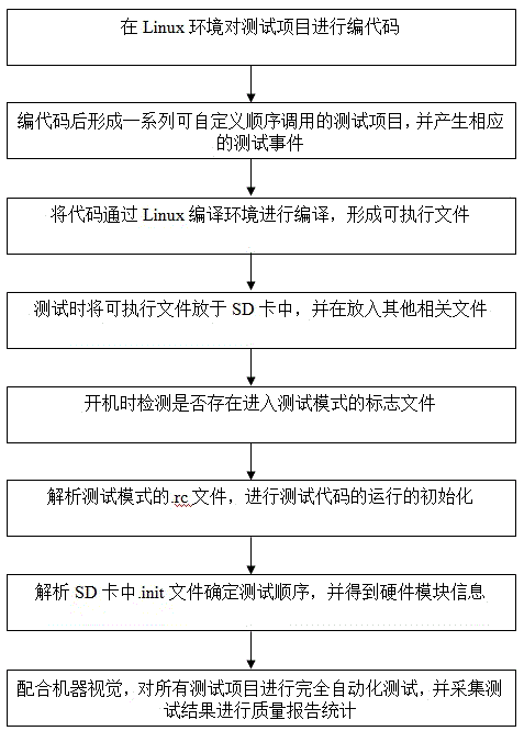
The invention relates to a method for automatically testing a hardware module of an intelligent displayer. The method comprises the steps of 1, encoding test items in a Linux environment; 2, forming a series of test items which can be called in a user-defined sequence after encoding, and generating corresponding test events; 3, compiling codes in a Linux compiling environment to form an executable file; 4, placing the executable file in an SD card during testing, and placing other relevant files; 5, detecting whether a logo file entering the test mode exists during starting; 6, analyzing a .rc file of the test mode, and initializing operation of test codes; 7, analyzing a .init file in the SD card to determine test sequence and obtain hardware module information; 8, conducting fully-automatic testing on all the test items based on machine vision, and acquiring test results for quality report statistics. According to the method, operation is easy, automatic testing of all the test items is achieved, and manual tracking and tracking are not needed during item testing.

Description

technical field [0001] The invention relates to a method for realizing automatic testing of intelligent display hardware modules. Background technique [0002] The traditional smart display test method can not achieve complete automation. Among them, the APP test method needs to install the test APK in the system. After the test is completed, the system needs to be reset, which consumes extra time. At the same time, the touch screen cannot be automated. Test; the rest of the automation There are also parts in the test that require human tracking and human operation. These deficiencies make the traditional testing methods unable to achieve complete automation, and the cost is high. Contents of the invention [0003] The purpose of the present invention is to overcome the deficiencies of the existing testing methods and provide a method for realizing automatic testing of intelligent display hardware modules. human Resources. [0004] In order to achieve the above object, ...

Claims


Application Information

Patent Timeline
Patent Type & Authority Applications(China)
IPC IPC(8): G06F11/22
Inventor 郭太良林志贤林金堂郭明勇叶芸徐胜姚剑敏
Owner FUZHOU UNIV
Learn More